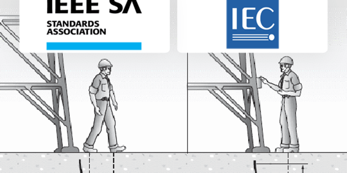
The definition of “touch voltage” is the voltage between accessible exposed and extraneous conductive parts that may lead to the risk of electric shock in the event of an electrical fault. This article covers AS/NZS 3000, BS 7671, and NFPA 70E rules concerning touch voltages and provides the equations for calculations.
This article explains how to calculate the current rating of cables in J-tubes. Typically J-tubes are the thermal bottleneck of submarine power cable routes.
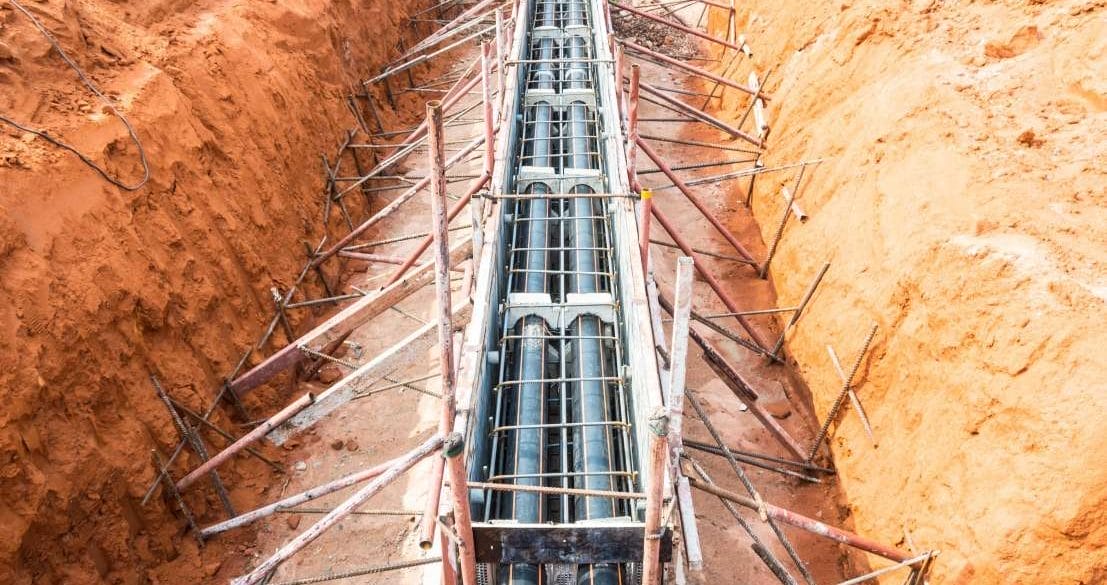
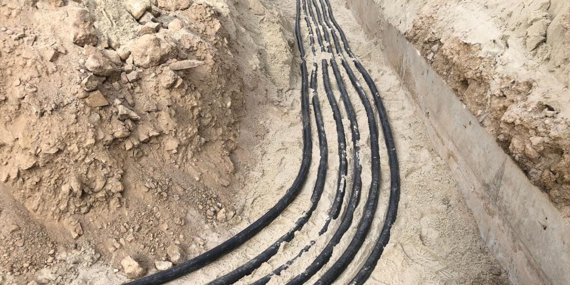
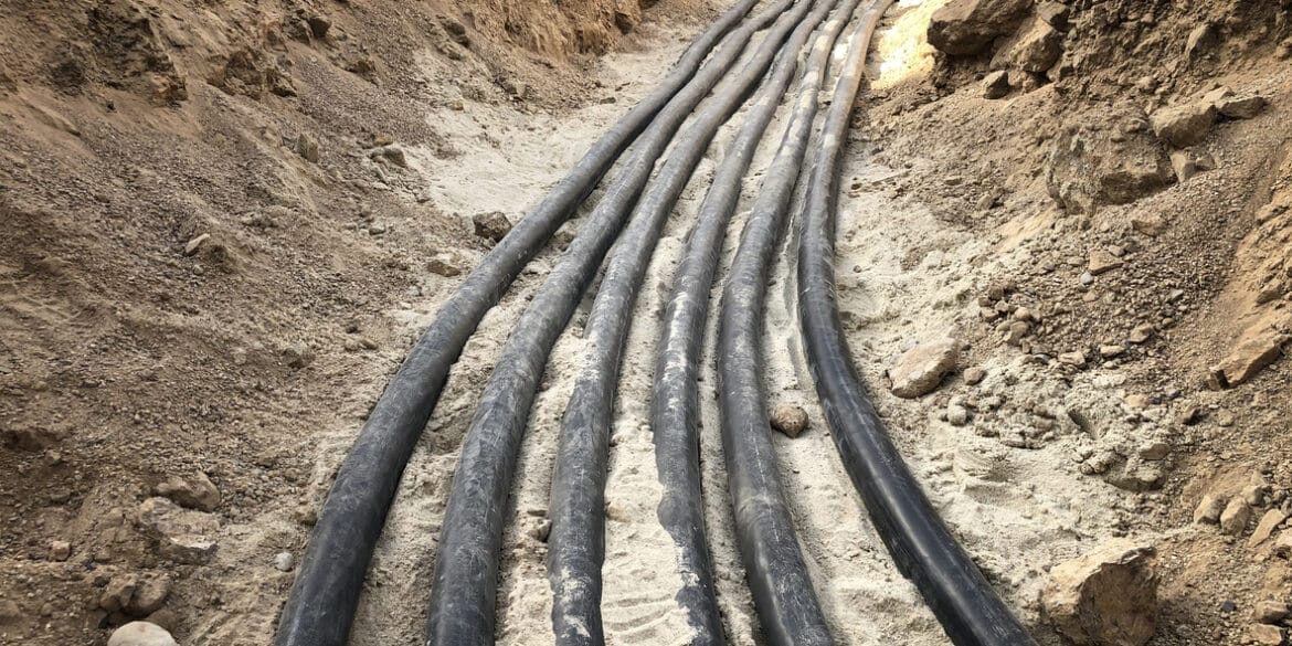
A new calculation method based on FEM and IEC 60287 for current rating of HV cables in soils with multiple different thermal resistivities is explained with an example calculation. Modelling the different soil thermal resistivity zones (multiple backfills) is important for obtaining accurate cable current ratings.
DC cable sizing has significant implications on a PV system's performance, total cost, and safety. Example calculations of Current Rating and Voltage Rise have been provided.
One of the main factors determining the severity of an arc flash injury is the proximity of the worker to the arc flash, also known as the working distance. Working distances from AS (ENA), IEEE, NFPA and DGUV Standards and Guides have been provided.
The effects of lightning strikes on earthing or protection systems designed to IEC 62305 can be modelled using an equivalent single frequency from 25kHz up to 1MHz which gives similar results to a time-domain approach. This article provides the frequency and current values to be used for modelling lightning.
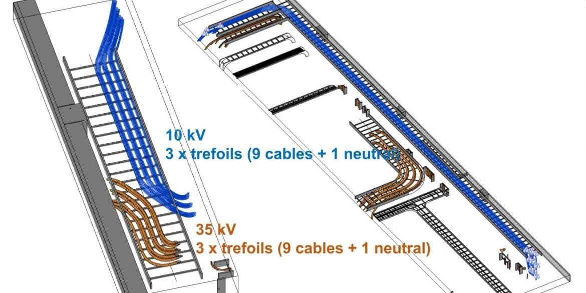
The methods for calculating the current rating of multiple cables installed in ventilated tunnels are explained with example calculations. Overall tunnel length and air velocity inside the tunnel have a significant impact on cable current ratings.
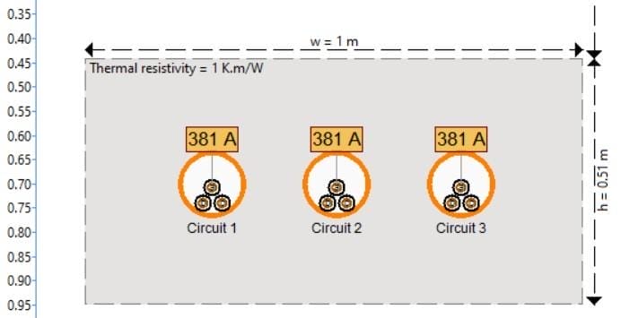
The calculation of current ratings for groups of (multiple) cable circuits require the quantification of the mutual heating component between the groups of circuits. This example is for multiple groups of circuits in air on the same cable ladder. This article will discuss the IEC 60287 approach.
A report investigated 6214 cable failures over a 14 year period. The main causes were insulation breakdown, excavation, joints or switchgear failure. The results may surprise you.
The effects of lightning strikes on earthing or protection systems designed to IEC 62305 can be modelled using an equivalent single frequency from 25kHz up to 1MHz which gives similar results to a time-domain approach. This article provides the frequency and current values to be used for modelling lightning.
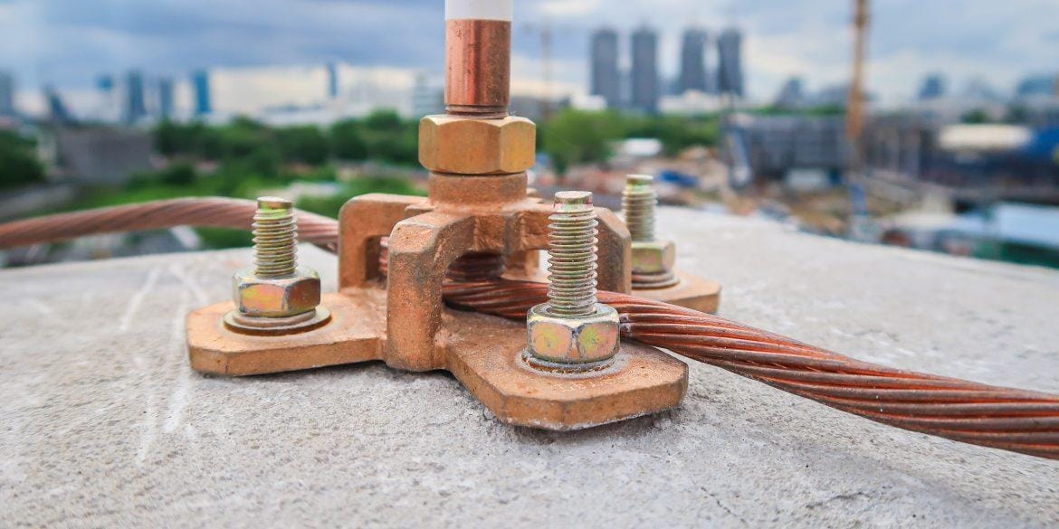
This report shows the effects of a direct lightning strike to an air terminal installed on top of a building which is connected to a buried earthing system.
Low voltage earthing systems include TN-S, TN-C-S, TT, IT and DC. High voltage earthing includes solid, ungrounded, resistance, reactance and resonant.
This article shows the effects of soil resistivity and thickness of layers on grid resistance for earthing systems in multilayer soils. Increasing the resistivity of soil layers tends to increase the grid resistance, no matter which soil layer that is. Increasing the thickness of any soil layer with high resistivity also increases grid resistance and if the soil layer thickness is increased for a low resistivity layer then the grid resistance will decrease. Software modelling is performed and the results are compared and shown to match well with those from CDEGS software.
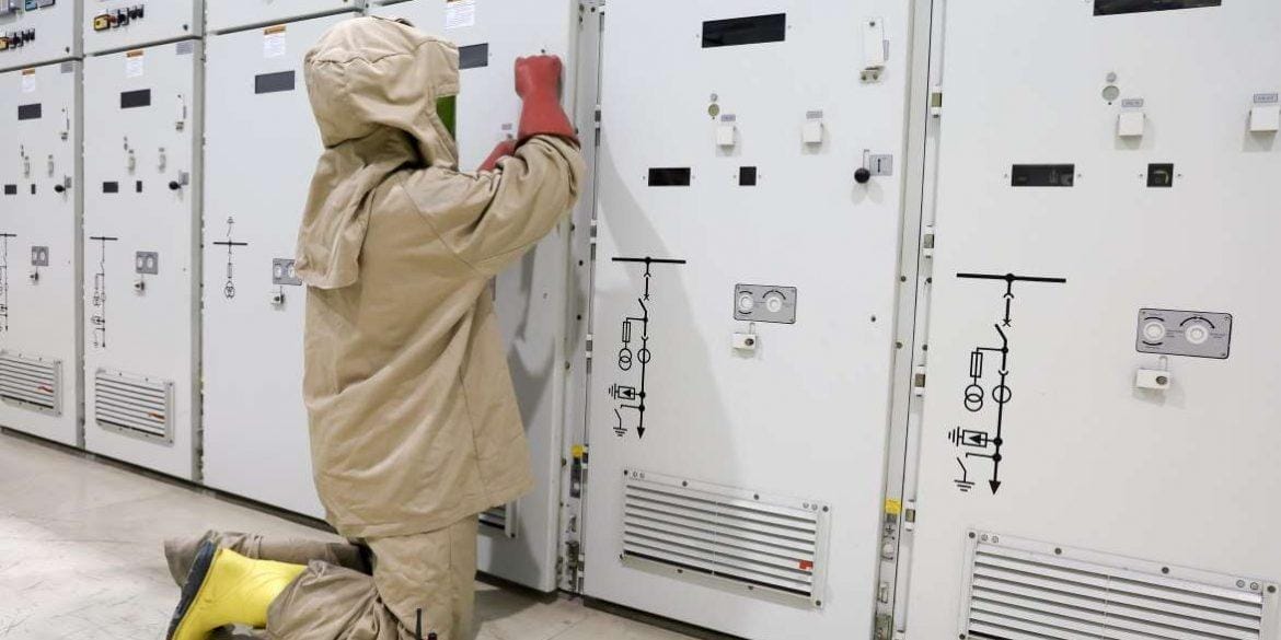
Electrical equipment operating at or above 50 V AC or 120 V DC which will not put into a deenergised state during work must be evaluated for arc flash and shock protection. Three types of activities of workers carry the highest risk of arc flash. Three main factors determine the severity of an arc flash injury.
Equations and method with all steps for accurate voltage drop calculations including power factor, cable operating temperature, resistance, reactance, DC, 1-phase or 3-phase, balanced/unbalanced with calculation examples provided.
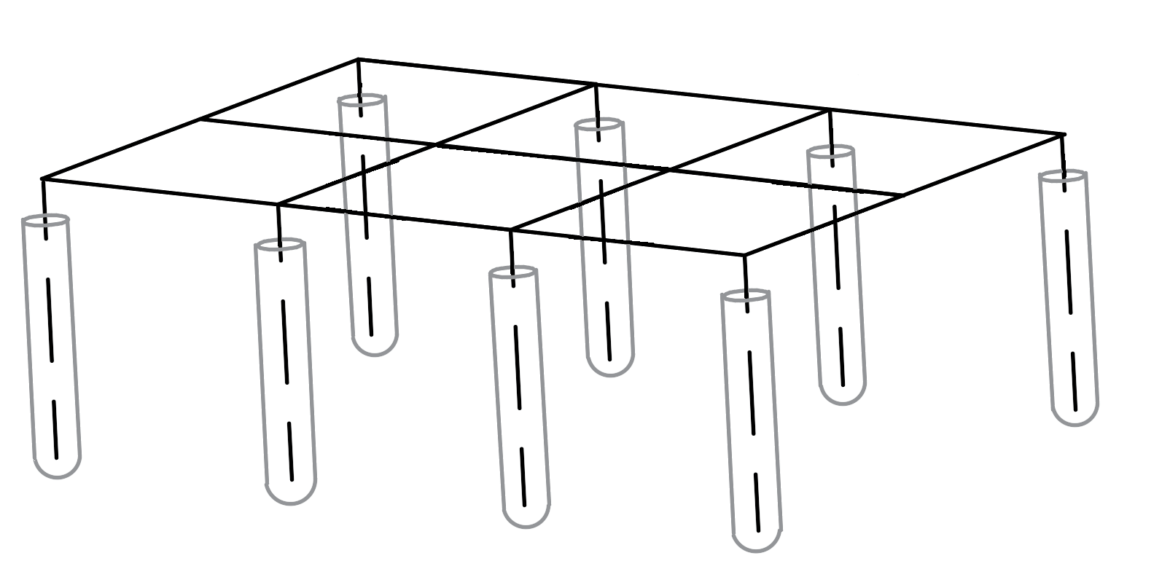
Earthing rods improve earthing systems when driven into low resistivity soil layers. Due to the proximity effect the rule of thumb is earth rods should be separated by at least their driven length. Rods may be encased in concrete to lower their resistance. Equations are provided for hand calculations and these have been validated with numerical software.
Charging current in power cables is 10-20 times larger than for overhead lines. The maximum length of cable circuits is determined by their capacitance. This report provides equations and shows how critical cable length depends on voltage level, cable size and frequency.
Soil electrical resistivity varies based on several factors. Use these tables to validate your soil measurements or devise a soil model without having measurements for preliminary earthing/grounding designs.
This article provides typical values for surface layer resistivity to be used for earthing and ground electrical calculations of touch and step voltages.
This article explains how to properly size earth conductors for earth faults and includes the method, equations, constants you can use and worked examples to follow.
We compare the best and latest earthing and grounding system design software including SafeGrid, CDEGS, XGSLab, ETAP and more based on technical features and compares price.
The effects on the current rating of cables buried in soils with different thermal resistivities are examined with software using the finite element technique.
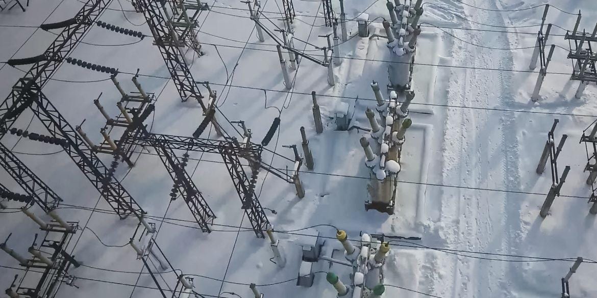
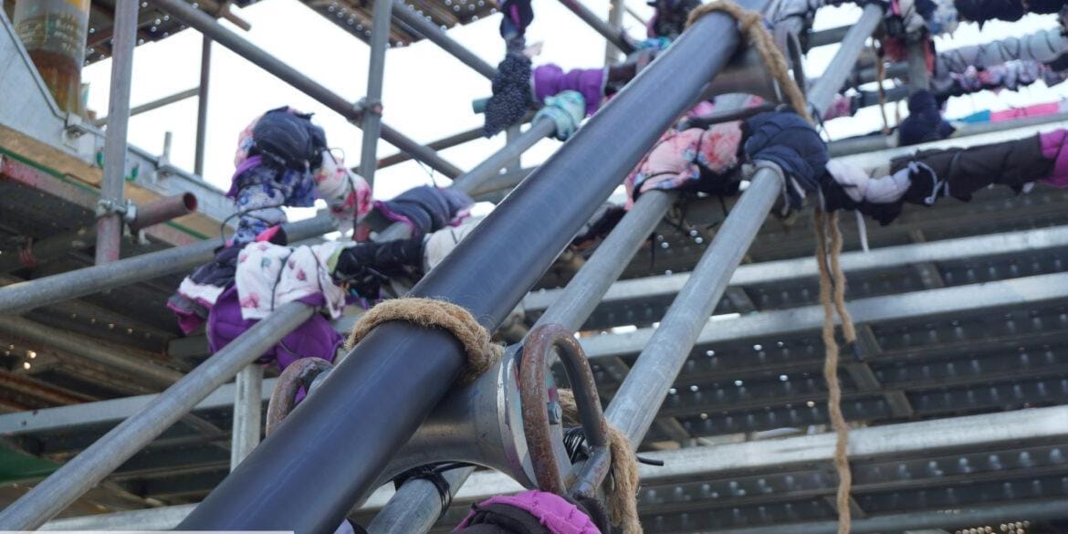
Soil resistivity is one of the most critical factors affecting earthing and grounding system performance and safety. In cold climates, the top-soil layers may be frozen during the winter or spring seasons, and resistivity may increase to as high as 10,000 Ω.m in the frozen soil layers. This can give rise to significant touch voltage hazards during an earth fault.
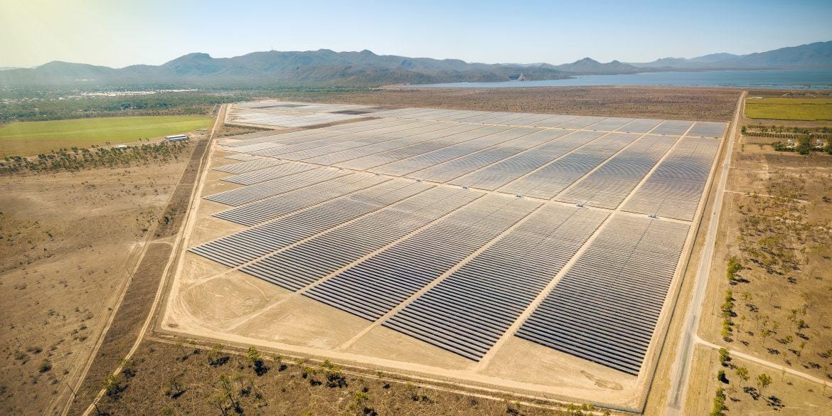
How to design and model earthing systems for a solar PV farm to the latest practices and standards. Soil resistivity, fault levels, and safety are covered.
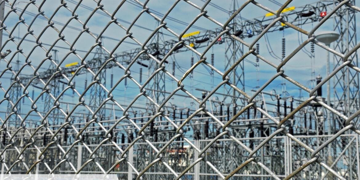
Should a metal fence be bonded to the substation earth grid? The metal fences around substations keep people out but they pose earthing safety challenges. These metallic fences, which are easily accessible to the public and personnel, must be adequately earthed and touch voltages on them during an electrical fault must not exceed safe limits.
Metal earthing rods that are encased inside concrete will have a lower resistance. Concrete has a typical electrical resistivity of between 30 Ohm.m to 200 Ohm.m.
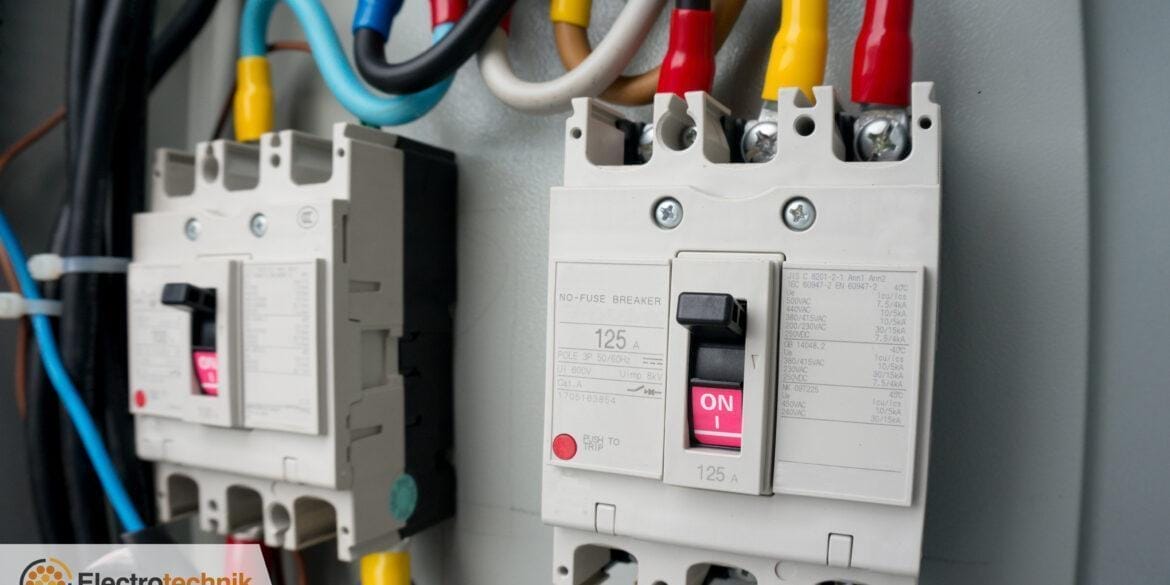
There are several international Standards (AS/NZS, BS and IEC) which cover requirements for protection coordination of low voltage electrical systems and this article provides a summary of those as a reference.
We have benchmarked our SafeGrid Earthing Software results for a 60 x 60 m grid against well-known software XGSLab™ and CDEGS™. We show that the results for grid resistance in multilayer soils up to 5 layers are virtually identical.
The definition of emergency rating is the permissible short-term rating of a cable already loaded and at a steady-state, considering the thermal capacitances and the thermal resistances of an installed cable system. The definition of cyclic rating is the maximum current of a cable when the load is varied in a sequence of steps that are repeated cyclically. The cyclic rating differs for different sequences and different cycle periods. Both emergency and cyclic ratings deal with time-varying loads
This article explains why dynamic ratings are important when dealing with long AC cables for wind farms. An example calculation of a dynamic rating which uses the measured load profile is given.
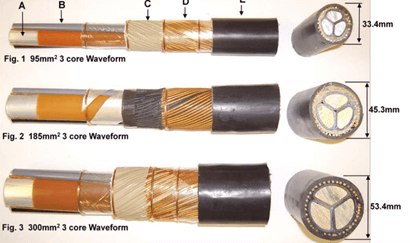
Waveform cables are commonly used in the UK for low-voltage power networks. The term waveform refers to the way the neutral/earth wires are laid around the cores/bedding. Using this configuration enables the neutral/earth wires to be opened so a connection can be made to the conductors anywhere along its length.
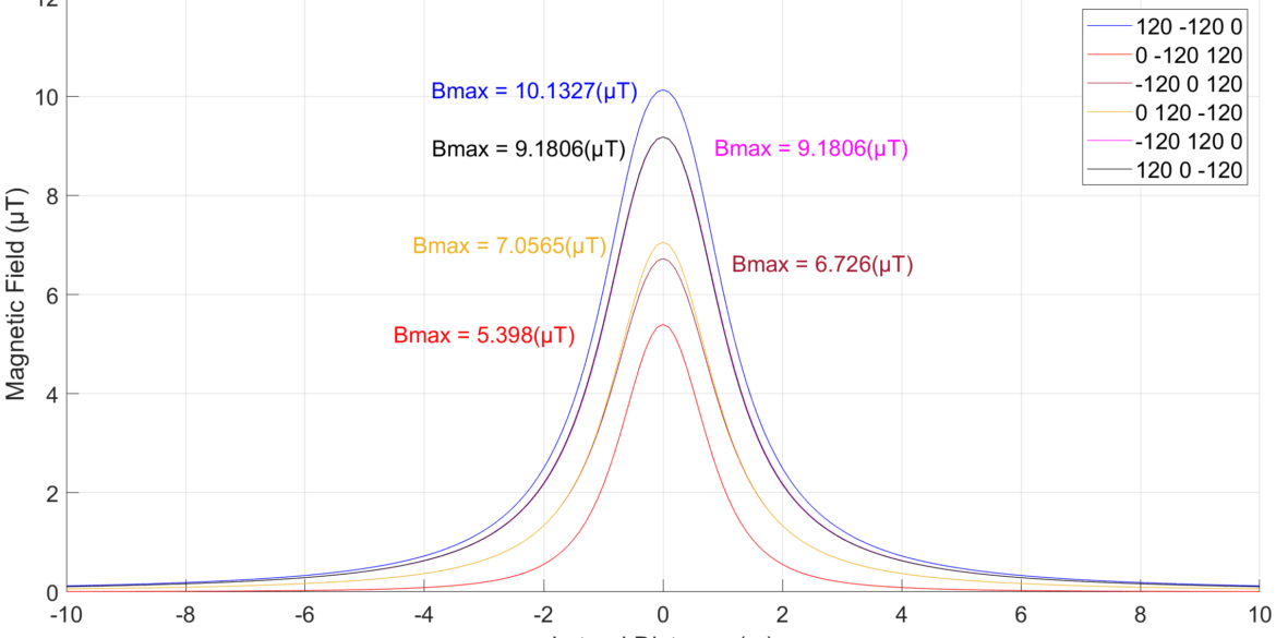
This article analyses the magnetic fields produced by electrical power cables installed in various configurations under varying conditions in the context of a health and safety-related issue. A software program has been used for calculating the results based on the Biot-Savart law. Techniques for the mitigation of magnetic fields are also presented.
Using bentonite to reduce resistance Sometimes it is not possible to achieve the desired reduction in ground resistance by adding more grid conductors or ground rods. An alternate solution is to effectively increase the diameter of the electrode by modifying the soil surrounding.
We have benchmarked our Cable HV Software current rating results for 110 kV cables against the well-known software CYMCAP. We have shown the results are virtually identical (under 1.5 % difference).
The new maximum demand module provides fast and accurate calculations for loads in accordance with rules from the Standards and for custom loads. An ingenious automatic phase balancing algorithm ensures maximum demand and phase imbalance are both minimised.
The Annex H in IEEE Standard 80-2013 contains benchmark case results for comparing and evaluating software tools and methodologies used for the analysis of substation earthing.
The results compare the simple equations from IEEE Std 80 with the results given by some of the commercially available software such as CDEGS, ETAP, SGW, SDWorkstation and WinIGS.
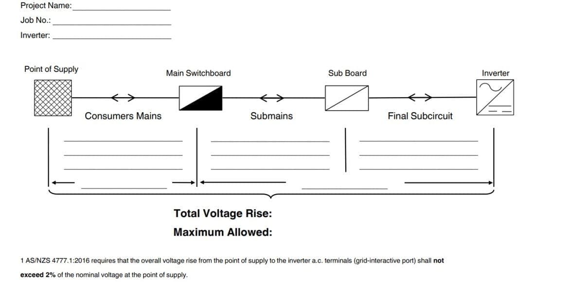
Voltage rise can occur in solar PV systems on the AC side between the power inverters and network connection point. Voltage rise calculations are no different to those for voltage drop.
Provides test procedures based on the fall of potential method and actual touch and step voltage measurements for the purpose of validating a safe earthing design. Includes procedures for both large or small earthing systems, safety requirements (for undertaking the tests) and recommended testing equipment.
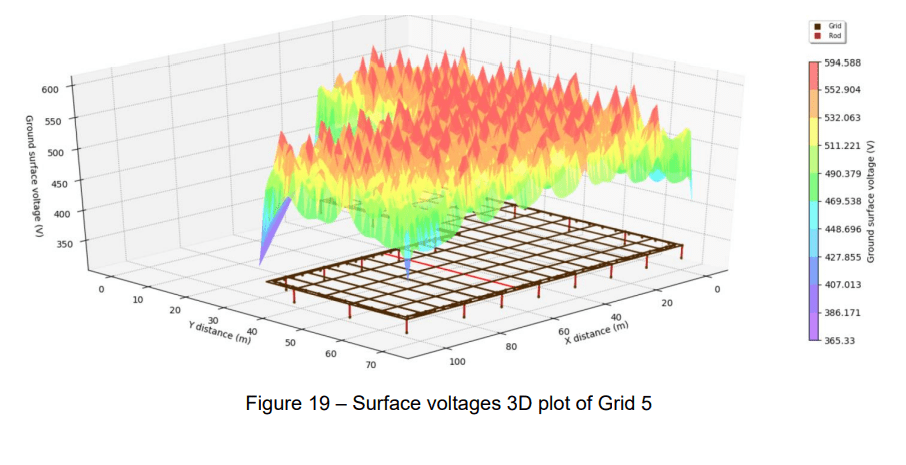
Key earthing design concepts covered including Grid Potential Rise, design to reduce touch and step voltages, fault current distribution, effects of soil resistivity and use of rods to improve safety along with calculation and modelling examples.
A safe earthing system design has two objectives; to provide a means to carry normal and fault current without exceeding equipment limits or adversely affect continuity of service and to reduce the risk of a person in the vicinity of an earthed facility being exposed to the danger of a critical electric shock.
The purpose of this document is to provide a better understanding of Fault Loop Impedance, also referred to as Earth Fault Loop Impedance so that the requirements of AS/NZS 3000 Wiring Rules for safety, design, installation and testing of electrical installation may be met.
Voltage Drop Limits per the Wiring Rules AS/NZS 3000 as well as rules of thumb to assist with electrical design. Includes AC and DC voltage drop or rise limits.
Derating factors are applied to the cable current rating ensuring that cable operating temperature limits are not exceeded. Derating factors are derived to match the specific cable installation conditions.