Table of Contents
Overview
Solar farms can cover large areas (up to tens of square kilometres) which presents both safety and economical challenges for design of their earthing/grounding systems.
! The cost of large-scale solar farm earthing systems can reach millions of dollars hence a small percentage of over design will introduce a significant extra cost.
In this article we are dealing with solar farms of 5 MW or greater in capacity. Meticulous design of the solar farms earthing system is required to ensure a functional system as well as personal safety during faults. Standard rules and guides apply for the practical earthing layout designs while the assessment of safety involves software modelling. For large solar farms modelling the earth grid will usually involve compromises such the use of as partial, limited, or approximate models (even with the most powerful and sophisticated software), however accurate results are still achievable.
Note that the same practical approaches to earthing used for safe earthing system design of a substation cannot be used for solar farms which is due to their very large size,which results in comparatively higher touch and step voltage hazards.
The modelling results in this article were performed using SafeGrid Earthing Software.

Description of solar farm electrical systems
The typical electrical system of solar power plants consists of several PV panels forming an array size of capacity 1-2 MVA that are connected to a common DC collection point which is then inverted to low-voltage AC to be transformed via a step-up transformer to medium voltage (commonly 11-35 kV). The AC power is transferred through a collector system of medium voltage cables to either switch gear panels or for large farms, back to a central substation.

Typical solar farm earthing systems
The standard earthing system of a solar farm is as follows:
The DC and AC sides of the system are galvanically (functionally) isolated. The DC side of the PV system may be either grounded or ungrounded. When it is grounded it is done at the ground fault protection device of the inverters. The DC and AC grounding systems of the solar system are usually bonded to improve the overall earthing system performance.
The main earthing system consists of buried bare copper conductors and rods (note earthing rods are rarely beneficial for solar farms), along with the above-ground interconnected metal panel support structures, support posts and cable trays. Unlike for a typical substation earthing system, the very large area covered by a solar farm makes it impractical to install buried meshes of conductors to achieve a near equipotential plane nor is it practical to install crushed blue metal rock everywhere on the surface to increase safety.
Each row of the solar panel array equipment and support structures is bonded to the main earth system either at each end or in some designs a continuous copper earth cable will be run from end-to-end of a row either above or below ground level.
! Note if the support structures are relied on as part of the earthing systems, then it must be ensured:
- The path between panels and supports is truly electrically continuous.
- Support posts must be protected from corrosion through galvanizing.
- Galvanic corrosion caused by contact between dissimilar metals such as copper and steel should be avoided otherwise “tinned” connections may be used.
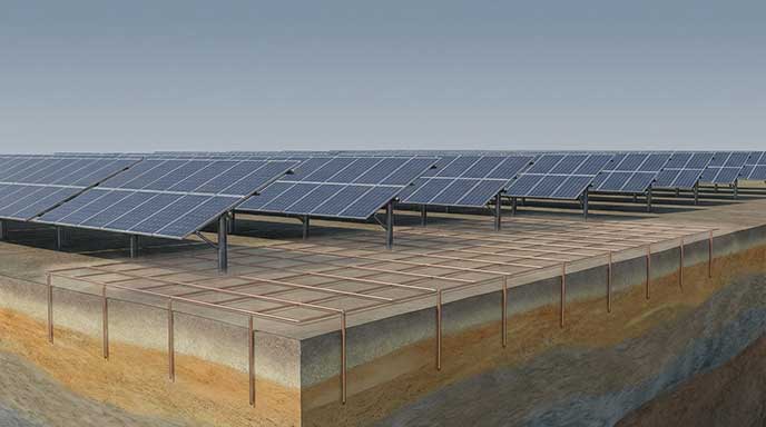
Figure 3 below shows a sample PV panel support structure (part of the auxiliary earthing). The red mark-up on the figure depicts how these structures have been included in the earthing model – the section of metal post in the ground is treated as a rod and these rods have related to insulated conductors.
Figure 3. Auxiliary earthing model

In general, the amount of buried earthing conductor installed for solar farms is minimized; just enough to bond each block of the arrays between the individual inverters and step-up transformers. A buried grading ring is typically run around the outside of any inverter/transformer equipment to minimize touch voltages.
If the solar farm has a substation for power grid connection, then this earthing system may be bonded together with that of the solar farm.
! Note that if the substation earth grid is interconnected with that of the solar farm, then faults from the HV side of the substation transformers need to be used in the modelling which will likely result in higher touch and step voltages.
Metal fences which surround the solar farms will typically require additional earthing and the fence earthing should be bonded to and installed as near as reasonably possible to the main earthing system to minimize the touch voltage hazards caused by nearby faults, transfer potentials or induction from transmission systems. For more information on the effect of fence installation, read Touch Voltage on Substation Metallic Fence.
Personnel safety hazards during earth faults
Similar safety concerns which occur during faults for substations exist for solar farms. The following hazards should be investigated for solar farms faults according to IEEE Std 2778 [1]:
- Touch voltages on all electrical equipment or earthed objects within the fence boundaries.
- Touch voltages on any nearby metallic fences whether connected or otherwise due to possible transfer voltages.
- Touch voltages earthed structures or equipment in the vicinity of the solar farm which may be affected by transfer voltages.
- Step voltages throughout and just beyond the entire solar farm installation.
Soil resistivity measurements and modelling
An accurate model or set of models of the soil electrical resistivity is required across the entire solar farm site in accordance with the methodologies described in IEEE Std 81 [2].
Multiple sets of soil measurements should be taken for short probe spacings (from 0.5 m up to about 30 m) across the entire site with separations between testing locations typically in the order of 500 m. These measurements at short spacings will help establish the soil model for the shallower soil layers.
It is also essential to get an understanding of the very deep soil layer resistivity. For substations, according to IEEE Std 80 [3], we use probe separations up to the overall diagonal width of the solar farm which would be impractical in the case of a solar farm. The IEEE Std 2278 recommends probe separations up to 300 m be used for solar farms or at least taking measurements until the of the resistivity of the very deep layer flattens out.
! It is always recommended to use a multi-layer soil resistivity model to closely match the actual soil structure for increased accuracy.
All measurement sets should be analysed separately, and an overall conservative model should be selected or derived. Table 1 of IEEE Std 2778 gives sample soil model development for a combined 3-layer soil model.
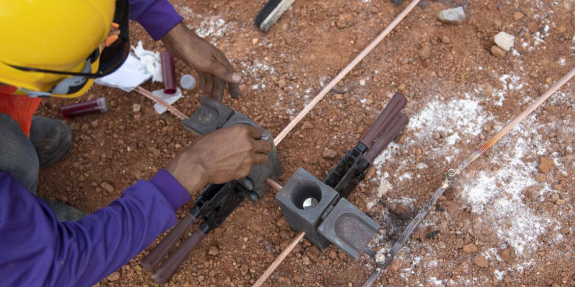
Figure 4. Measuring soil electrical resistivity for a solar PV farm site

Earth fault current level
An earth fault level investigation should be performed to establish a worst-case fault level scenario including magnitude, X/R ratio and clearing time which will be used for assessing safety. It turns out this investigation for a solar farm is not too dissimilar to that for a substation, with some important differences to be considered.
Faults on the LV AC systems including on step-up transformers or inverters may be high in current magnitude, but the ground potential rise (GPR) is limited to the LV system phase-to-earth voltage. Hence, in general faults on the HV or MV systems produce the worst-case scenario for personal safety in a solar farm and all the scenarios should be investigated.
If the substation earth grid is connected to the solar farm, faults on the HV side of the substation transformers will often be the worst case and result in the highest touch and step voltages.
Software modelling
As described earlier, the total solar farm buried earthing system comprises of various components. These include:
- Main PV grid–connects the earthing of groups of arrays and includes the transformer/inverter earthing.
- Auxiliary earthing – consists of the PV panel metal support posts which are buried and electrically interconnected with support structures or cables or both.
- Fence earthing system – consists of buried fence posts and grading conductor.
- Substation grid (if applicable) –typical meshes of buried conductor.
Having all the above components included into a software model for the earthing systems will result in the most accuracy, obviously. However, there will be a serious trade-off with the calculation time. It also may be impossible to model all the components, especially for extremely large and complicated solar farms in which case the modelling can be limited to a sample section of the total earthing system.
Including the auxiliary earthing in the model, especially, results in a significant reduction in the amount of earthing needed for the main PV grid component. The fence and the substation earthing also help with achieving a safe design.
Note: Modelling solar farms can be time-consuming. Refer to this knowledge base article on how to effectively and efficiently model solar earthing systems.
Example calculations
In the following example calculations, we will present grid resistance, Grid Potential Rise (GPR) and touch voltages for three main cases:
- Main PV earthing system only.
- Main PV and auxiliary earthing (PV array post and support structures) combined.
- Main PV, auxiliary, substation, and fence earthing combined.
The grid conductor models which were drawn in CAD and imported into SafeGrid for modelling are shown in the Appendix.
Common inputs:
Soil model – 3 layers (this is “Combined local model” from Table 1 in IEEE Std 2778-2020)
Top layer resistivity – 50 Ohm.m; thickness 2 m
Middle layer resistivity – 120 Ohm.m; thickness 33 m
Bottom layer resistivity – 65 Ohm.m
Conductors – 70mm2 bare copper conductor
Earth fault current – 1000 A, 50 Hz
Case 1. Main PV earthing grid
This case will have a grid size of 31600 m2 consisting of the main PV grid only. The calculated grid impedance is 0.829 Ω with a GPR of 828.9 V.
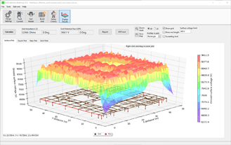
Figure 5 below shows that the maximum touch voltage is quite high at 732.3 V, caused by the large spacing between conductors (gaps) in the grid.
Figure 5. Touch voltage plot of the main PV earthing grid

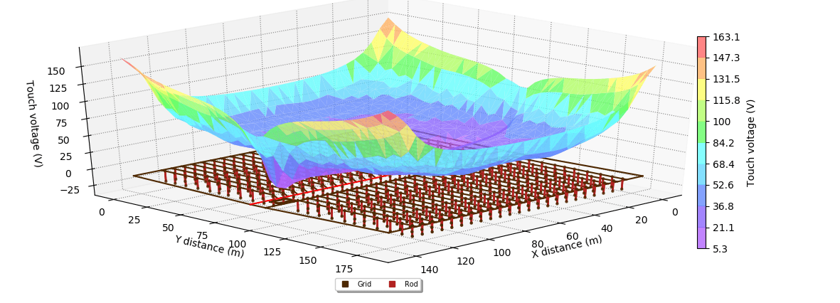
Case 2. Main PV grid with auxiliary post and supports
The array of auxiliary posts and supports was added to the main grid from the previous test. The posts were modeled as buried at a depth of 2 m and separated by 9 m. The spacing between array lines is 5.4 m and the total number of posts used is 506 posts.
The calculated grid impedance is 0.288 Ω with a GPR of 287.6 V.
Figure 6 below shows that the maximum touch voltage is much lower than the previous case at 163.1 V caused by a flattening in the surface voltage profile.
Figure 6. Touch voltages plot of the main PV grid with auxiliary support
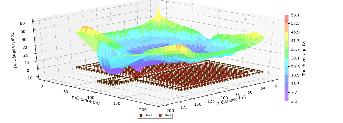
Case 3. Main PV grid, array post and supports, substation and fence
In the final case a typical medium voltage 20m × 20m, 16-mesh substation earth grid was added to the main grid and auxiliary earthing as well as a metallic fence placed 5 m away (as suggested by IEEE Std 2778-2020 for solar farms) from the main grid, and the separate fence earthing was bonded to the main grid at regular intervals.
The calculated grid impedance is 0.216 Ω with a GPR of 216.1 V.
Figure 7 below shows that the maximum touch voltage was significantly reduced to 58.1 V.
Figure 7. Power plant touch voltage
Summary of modelling results
Table 1 below provides a comparison of the results for the three previous test cases.
The calculation results show that including the auxiliary earthing, the substation and the fence earthing together in the model will help reduce touch voltages significantly.
| Grid model | Grid impedance (Ω) | GPR (V) | Maximum touch voltage (V) |
|---|---|---|---|
| Case 1 - Main PV grid | 0.829 | 828.9 | 732.3 |
| Case 2 - Main PV grid + auxiliary posts and supports | 0.288 | 287.6 | 163.1 |
| Case 3 - Main PV grid + auxiliary + substation + fence | 0.216 | 216.1 | 58.1 |
Validation testing of solar farm earthing
The substation earth grid can be tested after its construction and prior to the interconnection with the collector cable circuits and ECCs of the solar farm. Note that if the solar arrays are installed nearby to the substation (as they often are), there will be interference with the results.
Validation testing of an entire solar farm earthing system is challenging.
Current injection testing requires that a remote earth injection point be created at a distance of around 5 times the maximum dimension of the solar farm (several kilometres). This is very difficult to achieve at site for a solar PV farm earthing system.
IEEE Std 2778-2020 [1] concurs with the point above and states that validation tests of the earthing system for a large solar farm may not be needed if: Sufficient soil resistivity data was used for the design; and Accurate modelling and analysis were performed and well-documented.
Conclusions and recommendations
This article presents the recommended design for solar farm earthing systems with reference to the IEEE Std 2778-2020 and modelling techniques using software.
We have the following recommendations:
- Obtain accurate soil resistivity measurements along multiple traverses and derive an overall multi-layer soil resistivity model.
- Model the solar farm earthing arrangement as closely as possible to the actual installation and make sure you include the auxiliary earthing system including PV array support posts and structures.
- Review the relevant IEEE standards (refer to the References section herein).
Note that due to the large size of that post-construction validation testing of the modelling results (actual grid impedance, touch, and step voltages) is often not practical. Therefore, accurate software models are required to confirm our earthing system will be safe.
References
[1] “IEEE Guide for Solar Power Plant Grounding for Personnel Protection,” in IEEE Std 2778-2020 , vol., no., pp.1-24, 17 April 2020, doi: 10.1109/IEEESTD.2020.9068514.
[2] “IEEE Guide for Safety in AC Substation Grounding,” in IEEE Std 80-2013 (Revision of IEEE Std 80-2000/ Incorporates IEEE Std 80-2013/Cor 1-2015) , vol., no., pp.1-226, 15 May 2015, doi: 10.1109/IEEESTD.2015.7109078.
[3] “IEEE Guide for Measuring Earth Resistivity, Ground Impedance, and Earth Surface Potentials of a Grounding System,” in IEEE Std 81-2012 (Revision of IEEE Std 81-1983) , vol., no., pp.1-86, 28 Dec. 2012, doi: 10.1109/IEEESTD.2012.6392181.
Appendix: CAD drawings for software modelling
Case 1: Main PV grid earthing

Case 2: Main PV grid + auxiliary support posts and structures earthing

Case 3: Main PV grid + auxiliary + substation + fence earthing