Tutorial Video
Frequently Asked Questions
How do you select PPE for an arc flash hazard?
Body protection is required using arc flash-rated clothing when the calculated incident energy at the body is capable of causing a second-degree (curable) burn (1.2 cal/cm2 or above).
Based on the maximum calculated incident energy above (cal/cm2) you can select the appropriate PPE Category from the image below of the Electrical Arc Flash Hazard Management Guideline.
For alternative PPE categories refer to NFPA 70E and DGUV 203-077.
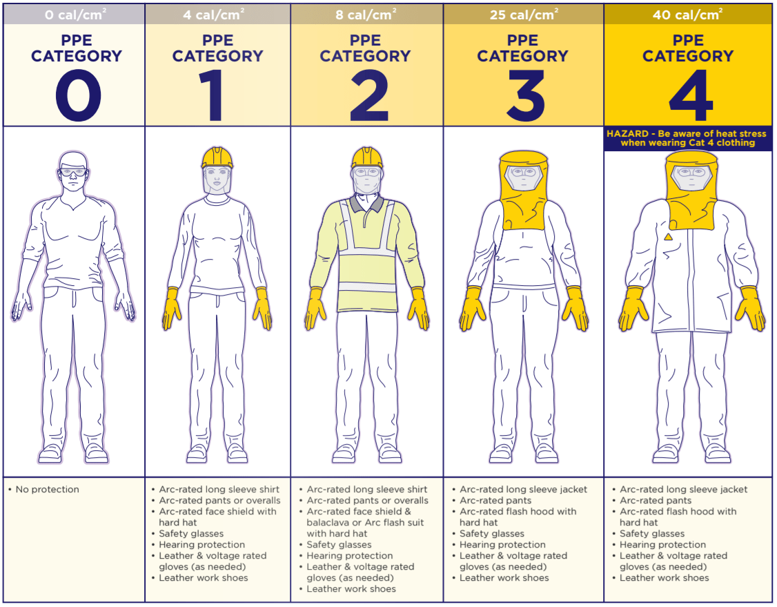
Figure 1 - PPE categories from the Electrical Arc Flash Hazard Management Guideline
How do you calculate arc flash for single-phase systems?
- The IEEE Std 1584-2018 model does not cover single-phase systems because arc-flash incident energy testing for single-phase systems has not been researched with enough detail to determine a method for estimating the incident energy.
- A conservative approach to finding the incident energy for a single-phase system is to use the single-phase bolted fault current and the voltage of the single-phase electrical system in this calculator which uses three-phase equations.
- The ENA NENS-09 guideline for arc flash analysis provides equations for calculating arc flash for single-phase systems.
How do you calculate arc flash for DC systems?
- To perform arc flash analysis for a DC system requires using a different calculation method other than from IEEE Std 1584.
- The DC arc flash calculation method from DGUV 203-077 (DC) and the Stokes Method both provide accurate results, whereas the Maximum Power Method provides conservative results.
- Both the Stokes Method and DGUV 203-077 (DC) perform multiple iterations to find the final arcing current whereas the Maximum Power Method provides only a simple constant multiplier for calculating the arcing current. Hence, the arcing current calculated by the Stokes and DGUV methods is more accurate compared to the Maximum Power Method (DC).
- Both the Stokes and DGUV 203-077 methods also consider the electrode gap when computing the arcing current which is not considered in the Maximum Power Method.
- ELEK Cable Pro Software can perform DC arc flash calculations.
Calculator inputs explained
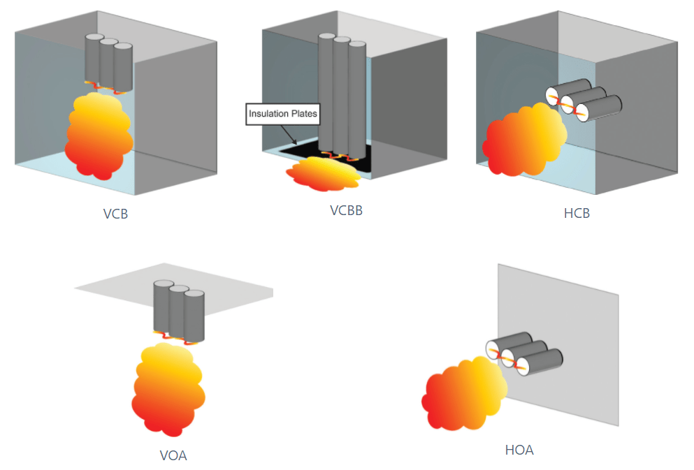
Electrode configuration
The orientation and arrangement of the electrodes.
- VCB - Vertical electrodes inside a metal box.
- VCBB - Vertical electrodes terminal in an insulating barrier inside a metal box.
- HCB - Horizontal electrode inside a metal box.
- VOA - Vertical electrodes in open air.
- HOA - Horizontal electrodes in open air.
Voltage (Vac)
System open circuit voltage. Three-phase AC voltage up to 15 kV for IEEE 1584-2018.
Fault current (kA)
The maximum prospective short-circuit current in the faulted switchboard. Up to 65 kA for IEEE 1584-2018.
Arcing time for Iarc (ms)
The total protection clearing time at arcing current.
Arcing time for Iarc_min (ms)
The total protection clearing time at reduced arcing current.
Working distance (mm)
The distance between the potential arc source and the face and chest of the worker performing the task.
Enclosure width (mm)
The actual width of the enclosure housing the electrodes.
Enclosure height (mm)
The actual height of the enclosure housing the electrodes.
Enclosure depth (mm)
The actual depth of the enclosure housing the electrodes.
Gap between electrodes (mm)
This is the distance between two electrodes or conductors.
IEEE Std 1584-2018 is applicable for electrode gap ranges of:
- 6.35 mm to 76.2 mm (for voltages 208 V to 600 V).
- 19.05 mm to 254 mm (for voltages 601 to 15 kV).