Table of Contents
Overview
This report explains how to perform accurate earth fault current analysis for substations connected by cable transmission lines. Earth fault currents for simple cable and overhead transmission lines are explained first. Next, two case studies involving hybrid cable transmission lines are presented.
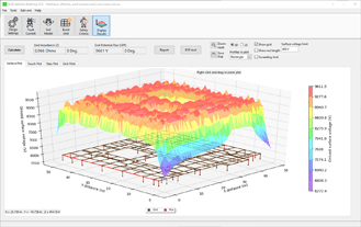
The calculations were performed using ELEK SafeGrid Earthing Software.
A circuit model approach is used by the software algorithms, where the transmission line is represented by its dimensional and electrical parameters and the mutual inductive and capacitive impedances are being considered, to solve for the fault currents and voltages.
Benefits of performing earth fault analysis
The earth potential rise (EPR), touch, and step voltages associated with an earthing system are directly proportional to the magnitude of the fault current flowing into and directly discharging into the soil by the earthing system. Therefore, it is important to determine how much of the fault current returns to remote sources via the cable screens or the overhead earth wires of the transmission lines feeding the substation.
In many cases, the portion of the fault current discharged into the substation earthing system will be lower (often substantially lower) than the maximum fault current available. This is the significant benefit of determining the actual fault current distribution.
If you can show that the fault current entering your earthing grid is significantly lower than the maximum fault current (often the case) this will dramatically reduce touch and step voltages (the requirements) and greatly simplify the design of the earthing system.
Cable transmission line construction
The high-voltage transmission lines connected between substations are predominantly constructed with overhead powerlines, this is due to the comparatively high cost of power cables. However, in urban areas, where it may be impractical or unsafe to use overhead lines, or when passing through environmentally sensitive areas, either an entire transmission line may be constructed with underground power cables or sections of underground power cable may be incorporated into an overhead transmission line.
There are three common transmission line configurations used for urban areas :
Underground cable link between two substations.
A substation is fed by an overhead line through an underground cable link.
An underground cable link is in the middle of an overhead transmission line (siphon system).

Transmission line earthing systems
Along transmission lines there are earthing systems (electrodes) installed in the following locations:
Terminating substations.
Overhead tower footings.
Cable bonding points or joint bays.
Transitions between overhead and underground.
Overhead transmission towers each have dedicated earthing systems and for overhead lines with earth wires, these are electrically interconnected.
For AC power cabless utilising cross-bonded sheath/screen arrangements, joint bays which have their earthing system is implemented to reduce circulating currents in the cable sheaths.
Refer to our article on Sheath Bonding Design Guide for High Voltage Cables.
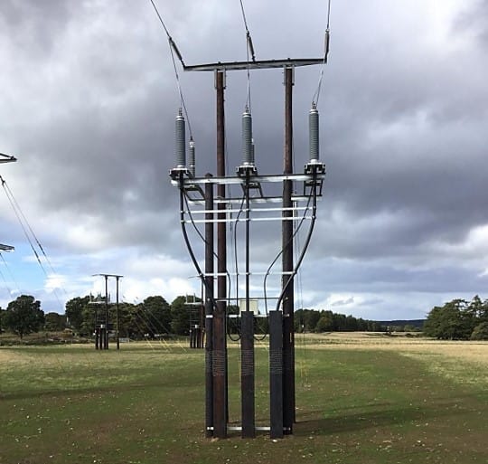
The transition between underground cables and overhead lines occurs at either transition poles for medium voltage (MV) or above-ground ancillary facilities such as cable-sealing end compounds or cable-sealing end platforms typically with metallic security fences for high-voltage (HV) transmission lines. For guidance on the design requirements of OH/UG transition stations refer to IEEE Std. 1793 [ref. 2].
Earth fault currents and earth potential rise
When an earth fault occurs in a transmission system, the fault current will return to the source via the metallic return paths (earth wires of overhead lines, sheath/screen/armour of power cables, earth continuity conductors (ECCs)) and through the earth itself via the buried earth electrodes.
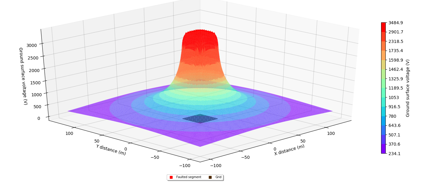
The current injected into earth electrodes causes an increase in potential concerning the reference earth. The resultant flow of current through the surrounding soil will cause the earth’s potential in the vicinity of the electrode to rise. This EPR will decrease with the distance away from the electrode.
Two substations connected by cable transmission line
The current in the core of a single-core cable or the unbalance of current in the cores of a multicore cable induces a voltage in the metallic layers such as the sheath, screen, and/or armour of the cable. If the cable sheath is bonded at both ends, a current will flow which constitutes a portion of the earth fault current returning to the source, where the remainder flows through the earth via the earth electrodes. The quantity of current returning in the cable sheath is, inter alia, dependent on the location of the cable in the system concerning the source of fault current infeed and the position of the fault as well as on the values of the terminating substation earth resistances.
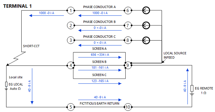
The electrical circuit schematic of a simple cable transmission line connected between two substations is shown in Figure 3 and depicts the distribution of a 1000 A current when a fault occurs at one end, the Local site (terminating substation). Notice that 96 % of the total returns to the current source via the cable screens. The return current on SCREEN A carries the highest portion of the current (656 +334 i A) compared with the other screens because it is physically nearest to (and hence has the highest magnetic coupling with) the faulted PHASE CONDUCTOR A.
Two substations connected by overhead transmission line
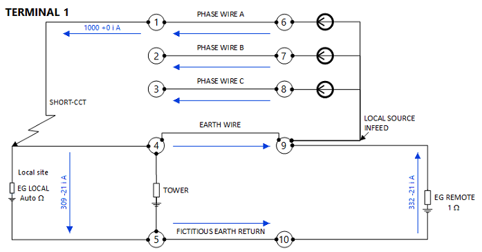
The same principles apply when an earth fault occurs for an overhead transmission line connected between two substations. The schematic shown in Figure 4 depicts the fault current distribution for a 5 km long overhead transmission line with a single earth wire and 500 m between spans (towers). Notice that 31 % of the fault current (309 -21 i A) enters the earth electrode EG LOCAL, compared with only 4 % for the cable transmission line. Because of the relatively low magnetic coupling between the earth wire and phase wire (due to large physical separation) and the high electrical resistance of the earth wire conductors, they carry a smaller portion of the fault current.
Hybrid cable transmission lines
The distribution of earth fault currents in hybrid transmission lines with overhead and underground cable sections and/or multiple sections with different sheath bonding configurations is important to analyse.
High EPR occurs at UG/OH transition stations caused by the difference in the earth return currents between the cable sheaths and earth wire(s). Case study 1 below demonstrates this case.
Due to similar reasons, high EPR can occur at the intersection between cross-bonded and single-point bonded sections of a cable transmission line. Case study 2 below demonstrates this case.
Case study 1 - Cable and overhead transmission line
This case study involved a 132 kV transmission line connected between two substations consisting of underground cables (UGC) with two 1.5 km cross-bonded sections and a 10 km overhead line (OHL) consisting of 500 metre spans with a single earth wire.
This case study shows high EPR occurs at the overhead and underground transition stations.
An equivalent circuit model is used to calculate EPR and earth grid (return) currents.
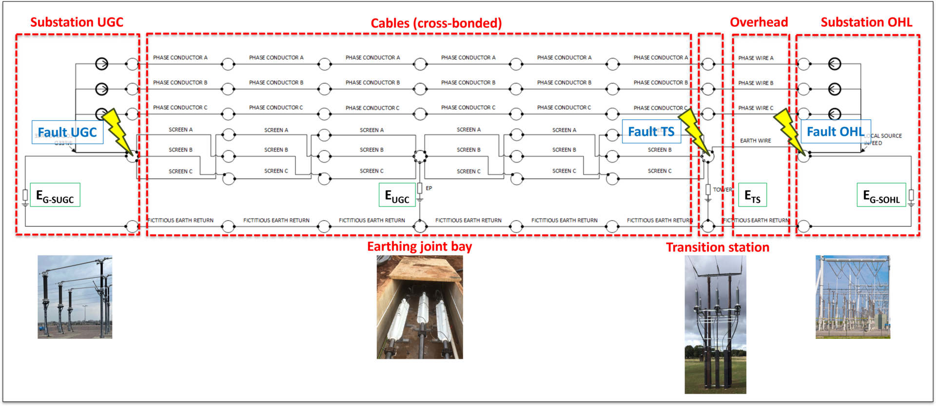
The earth resistance of the substations at both ends is 0.2 \(\Omega\) . The resistance at the earthing joint bay between the two major sections of the cross-bonded cable system is 10 \(\Omega\). The resistance at the UG/OH transition station is 1.56 \(\Omega\). The soil electrical resistivity along the transmission route is assumed to be uniform 100 \(\Omega\)m. The circuit parameters are in the software modelling guide.
EPR and grid currents during earth faults
The EPR and currents were calculated in the grid model for the following earth fault scenarios:
Faults at the UG/OH transition station fed from either substation or both substations (3 cases).
Faults at either Substation UGC or Substation OHL ends (2 cases).
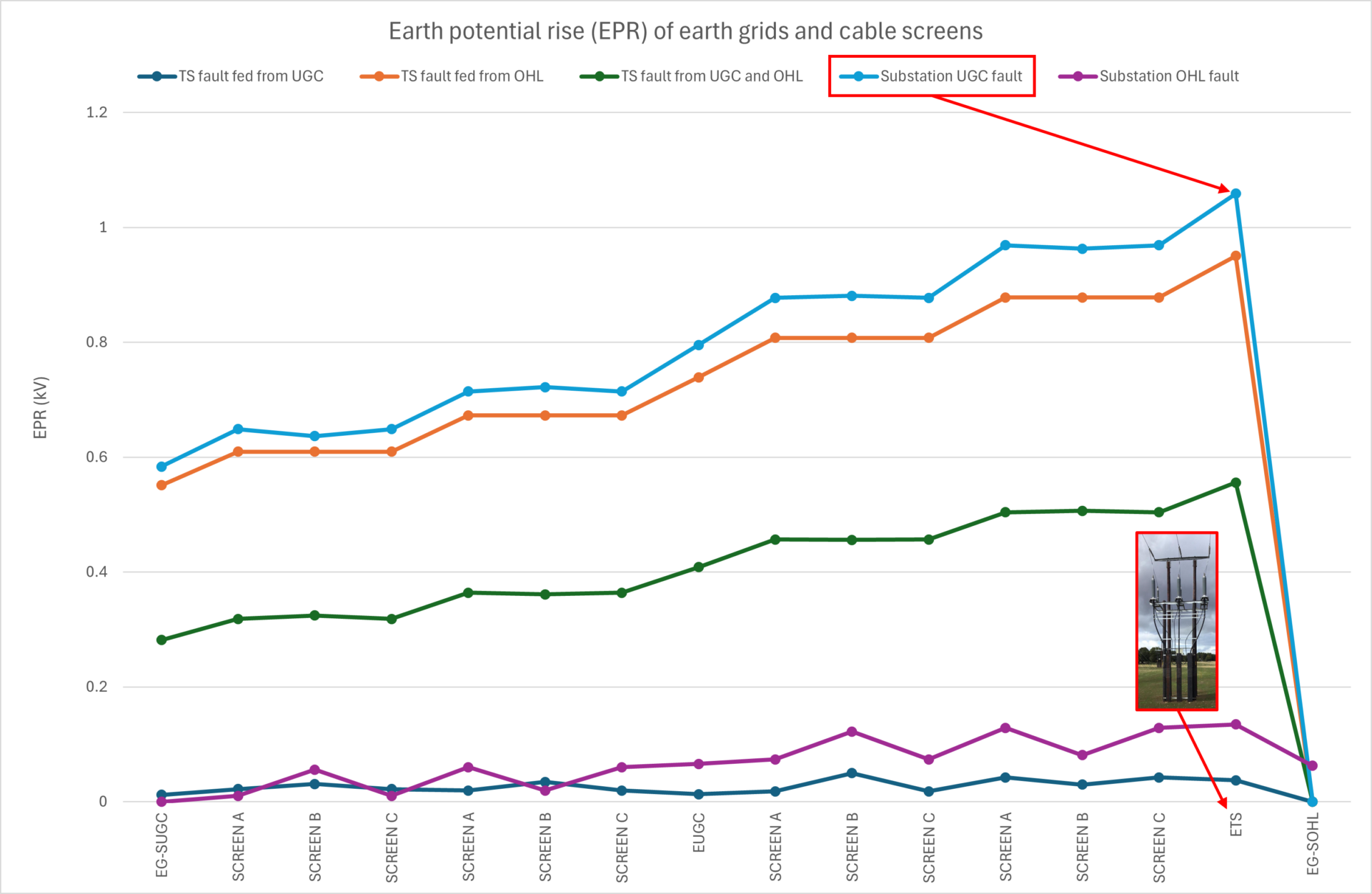
Figure 6 shows a plot of the EPR at the earth grids including at Substation UGC (EG-SUGC), cable earthing joint bay (EUGC), UG/OH transition station (ETS), and Substation OHL (EG-SOHL), as well as the EPR on the three cable screens (A,B,C) along the route.
For all fault scenarios the EPR at the UG/OH transition station was the highest of the locations.
An earth fault at the cable-connected substation (Substation UGC) resulted in the highest EPR which was at the UG/OH transition station. Importantly, it was not a fault at the UG/OH transition station that resulted in the highest EPR. The complete results are given in the software modelling guide.
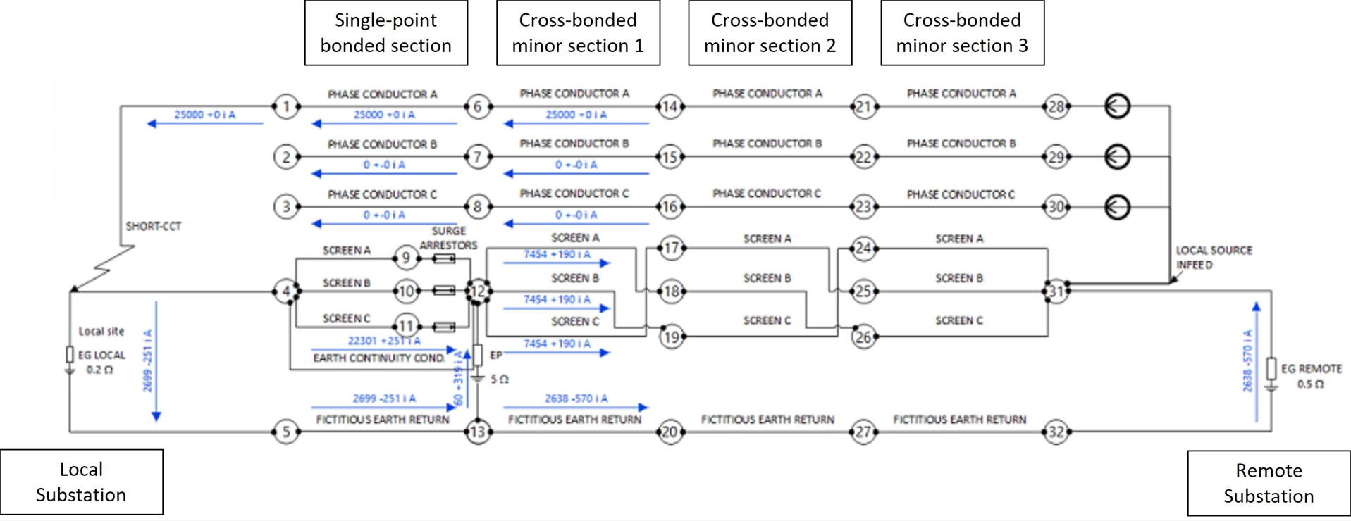
Case study 2 - Single-point and cross-bonded cable transmission line
This case study involved a 230 kV underground cable transmission line between two substations with two sections – one 1500 m long cross-bonded section with three equally-lengthed minor sections and a 500 m single-point bonded section.
The local substation (EG local) is connected to the single-point bonded section, and the remote substation (EG remote) is connected to the cross-bonded section. The impedances of the substation earth grids of the local and remote earth grids are 0.2 \(\Omega\) and 0.5 \(\Omega\), respectively. The impedance of the earthing point between the cross-bonded and single-point bonded sections is 5 \(\Omega\).
The circuit parameters are given in the software modelling guide.
A 25 kA earth fault was applied at the local earth grid (EG local) which was fed from the remote current source. Figure 7 shows a schematic of the cable transmission line and earthing system.
Screen resistance
Figure 8 shows EPR at the local and remote substation earth grids, and earthing point (joint) between the single-point and cross-bonded cable sections, for screen resistances between 0.02 and 0.4 \(\Omega/km\).
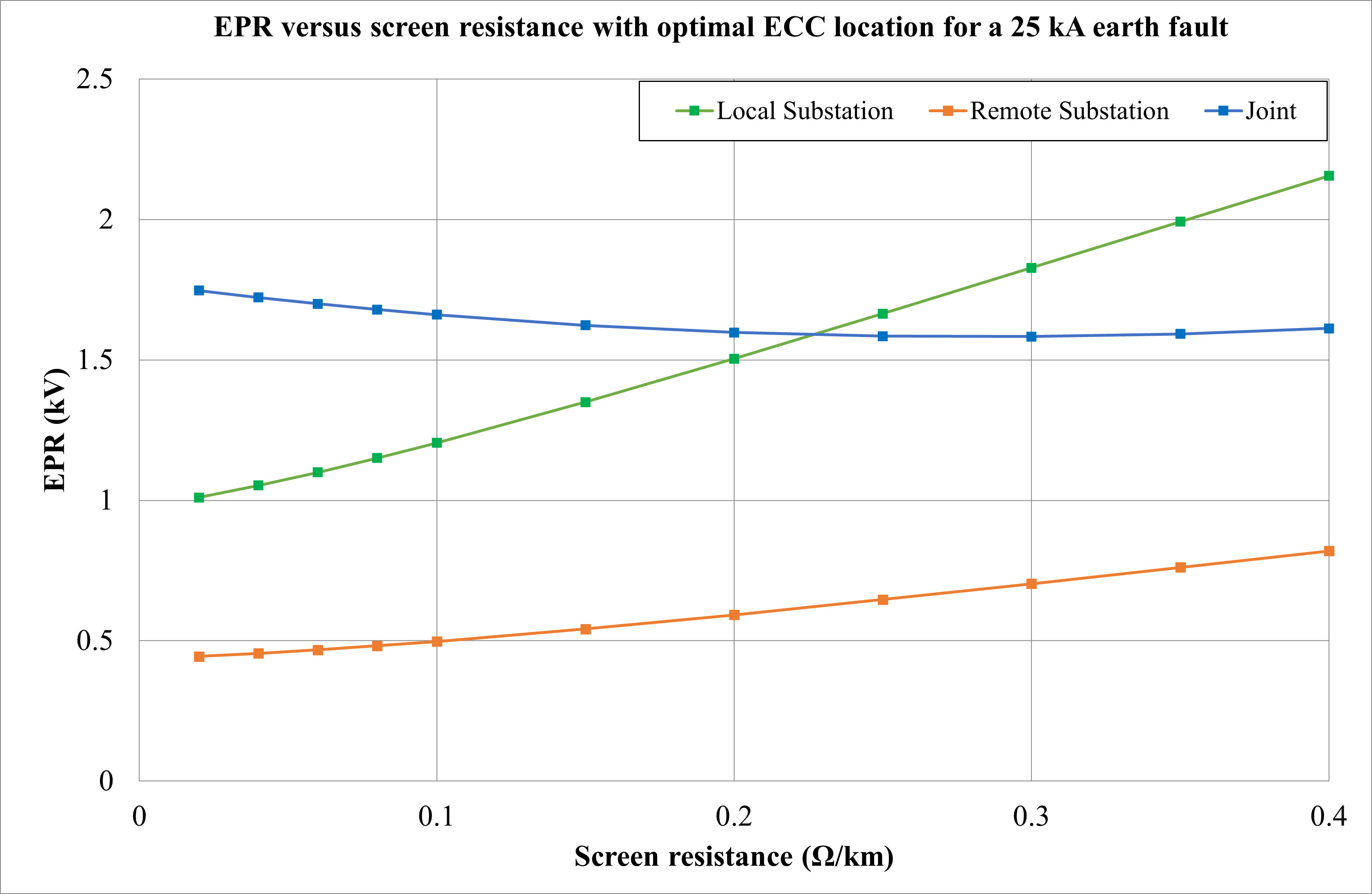
The EPR at both ends of the cable transmission line varied considerably with screen resistance.
As the screen resistance was increased, the percentage of current flowing through the earth path (Joint 3) increased. This in turn increased the EPR at both ends of the line (by 114.8 % and 84.4 % at the local and remote substations respectively). In the case of the joint, the EPR does not vary much with screen resistance (with the ECC in optimal location, a reduction of -7.6 %).
Figure 9 shows the magnitude of screen-to-earth voltages is significantly higher for the single-point bonded section compared with the cross-bonded section, which is not surprising. It is not shown here but the farther the faulted phase is from the ECC the greater will be the screen-to-earth voltage. The variation in the maximum voltages is less for the single-point bonded system than for the cross-bonded system. The variation in the maximum screen-to-earth voltages with the ECC in the optimal position is 25.29 % for the cross-bonded section and 4.16 % for the single-point bonded system.

ECC size and position
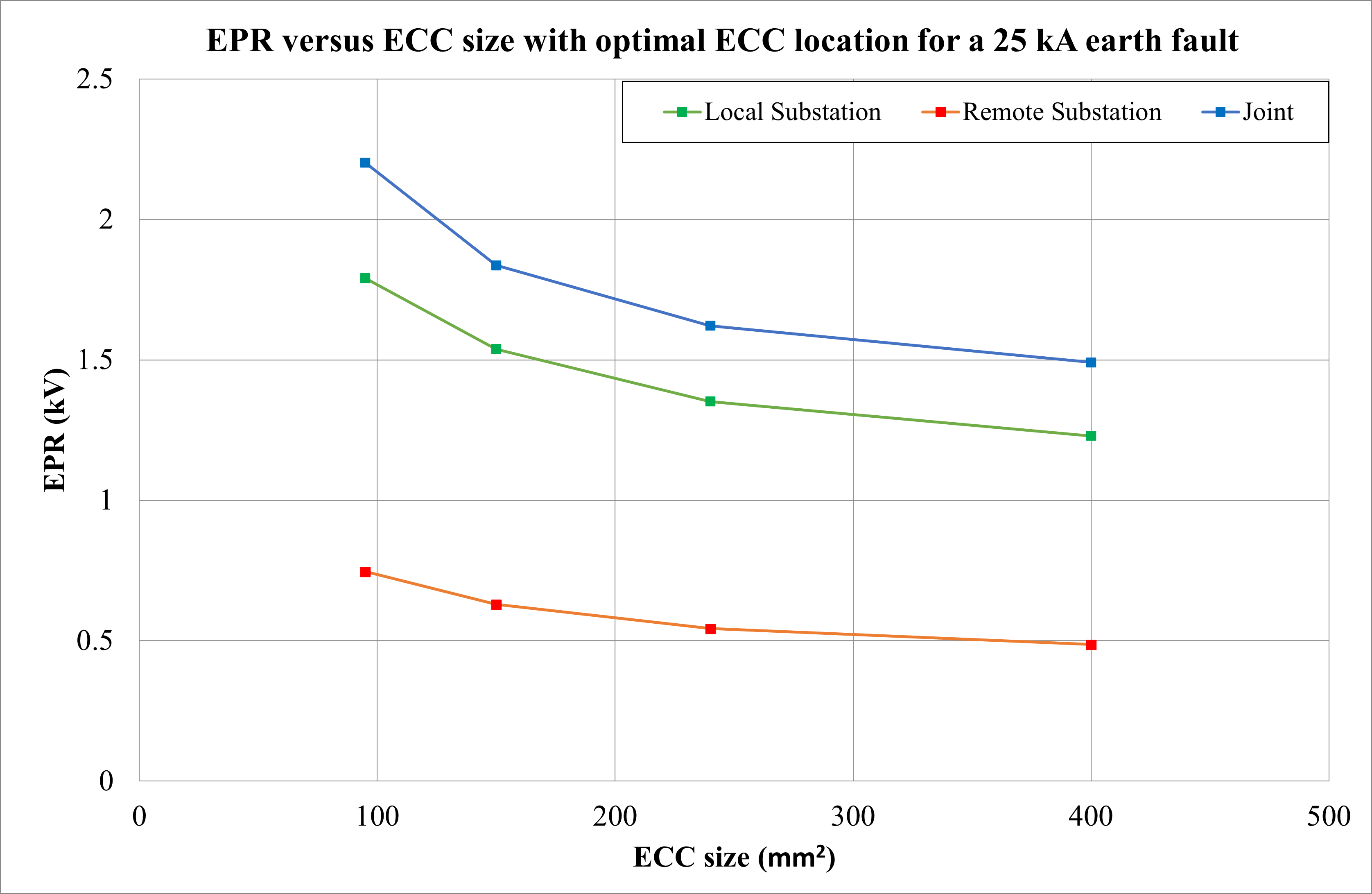
The minimum size of the ECC conductor must be sufficient to carry the full fault current of the cable system. Figure 10 shows the impact on EPR when ECC size was varied from 95 mm2 to 400 mm2 which results in a reduction in EPR of between 30 and 35 %.
It is important to optimally position the ECC. Refer to the Appendix on optimal ECC position.
With the ECC in an optimal position and transposed, the EPR at all points is lower. When the ECC is positioned outside of the circuit, the voltage at the joint increases due to circulating currents in the ECC. This negative effect on EPR tends to be worse if the ECC is located outside but still close to the cables of the circuit and even worse if the ECC is not transposed. The percentage difference in EPR of the joint, for a screen resistance of 0.15 Ω/km, for the ECC located 250 mm outside of the circuit was 265 % more than the EPR when the ECC was in the optimal position.
Earth resistance at joint
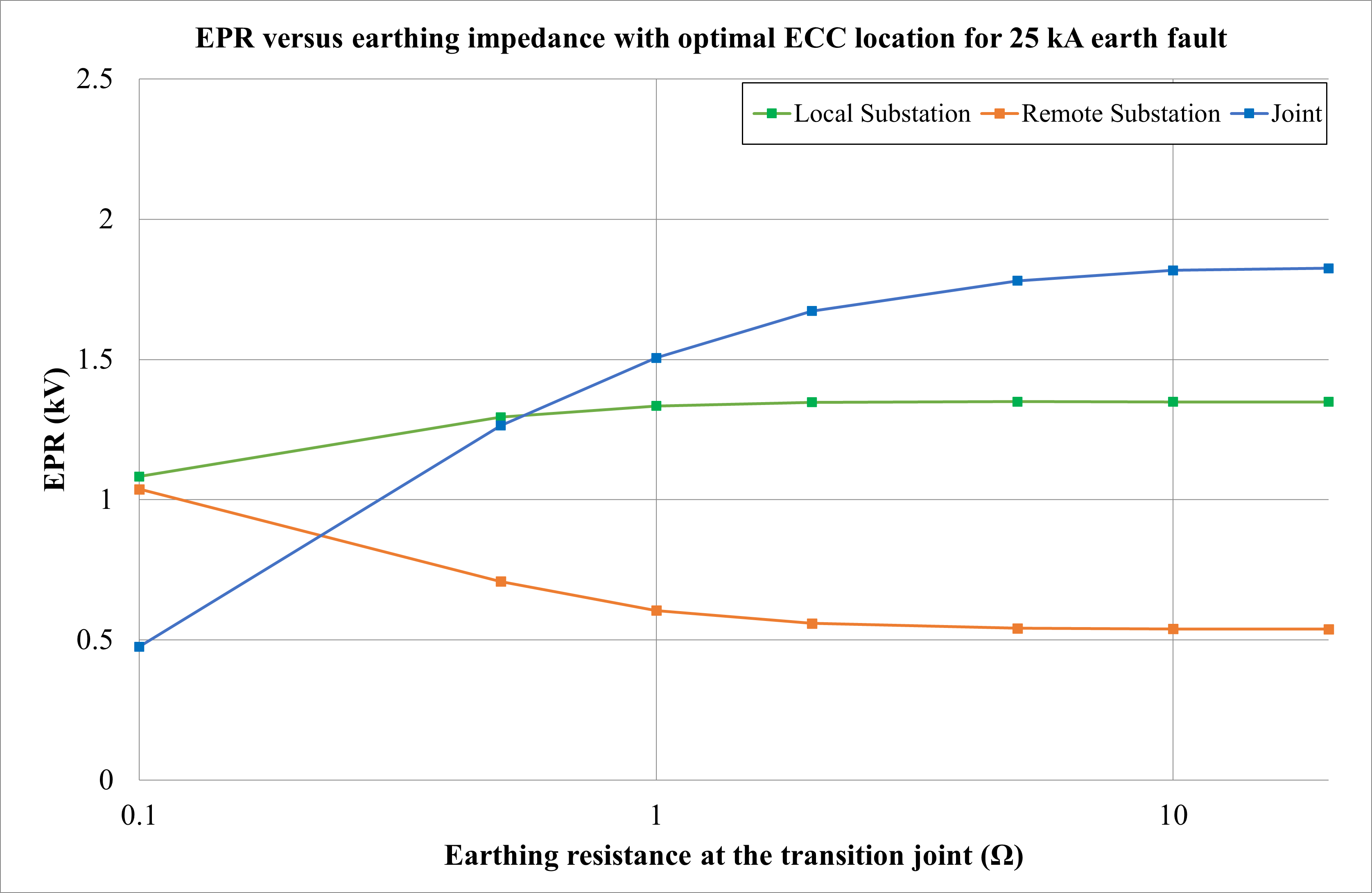
Figure 11 shows the variation in EPR when the earthing resistance at the joint between cross-bonded and single-point bonded sections (joint) was varied between 0.1 Ω and 20 Ω. All other parameters, in particular also the earthing impedance at both substations, remained constant.
As the transition joint resistance is increased the screen-to-earth voltage at the joint increases significantly by 282.6 %. The single-point bonded end of the cable transmission line is less affected than the cross-bonded end, with a moderate increase of 24.51 % and a decrease of 48.05 %, respectively.
Conclusions and recommendations
1. EPR of the earth grids is generally not a concern when substations are connected by a cable transmission line. This is because the majority of the fault current returns on the cable screens.
2. The EPR may be relatively high if substations are connected by an overhead transmission line.
3. The EPR is roughly half for a connection between substations, and where the fault current to be taken into account is only the fault current from the sound end and not the overall fault current.
4. Excessive EPR is likely to occur at an underground and overhead line transition of a hybrid transmission line or siphon system. The highest EPR at the UG/OH transition will most likely occur for a fault at the substation, not necessarily a fault at the transition itself.
5. For earth faults the influence of earthing impedance at the UG/OH transition point on EPR is significant.
6. If the ECC in the single point section is not optimally positioned and/or not transposed, there will be a circulating current induced in the ECC. This leads to increases in the EPR and screen-to-earth voltages, in particular at the transition between cross-bonded and single-point bonded sections.
7. Increasing the ECC size (or more than one ECC per circuit) will reduce the screen-to-earth voltages.
Appendix:
Optimal ECC position
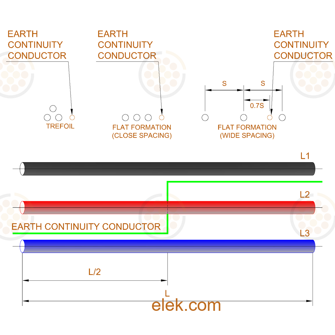
An earth continuity conductor (ECC) is an insulated conductor between the grounding points of a single-point bonded cable system to provide a continuous return path for fault current.
The size of the ECC conductor must be sufficient to carry the full fault current of the cable system. The spacing from the cable circuit should be close enough to limit the voltage rise of the sheath during fault. Since the ECC is exposed to magnetic induction from the phase conductors (like any other parallel conductor), it must be transposed during the route to reduce circulating currents and losses.
The optimal ECC position is depicted in the image below for common cable formations:
References
[1] Earth Potential Rises in Specially Bonded Screen Systems, CIGRE TB 347, June 2008.
[2] IEEE Std. 1793-2012, IEEE Guide for Planning and Designing Transition Facilities between Overhead and Underground Transmission Lines.
[3] ELEK SafeGrid Earthing Software, V8.0.