Table of Contents
Overview
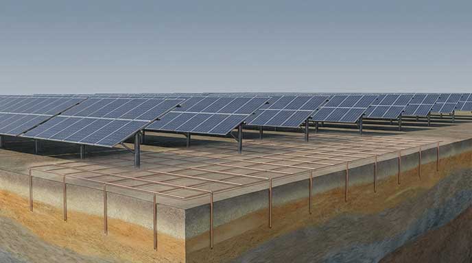
The typical earthing system for a wind farm is a single integrated (combined) structure suitable for all purposes, including lightning protection, power system fault protection, and telecommunication systems.
The WTGs are earthed locally, and a ring electrode is installed for controlling the ground surface voltage gradients close to the foundation. The earthing for the step-up transformers is bonded with the WTG earthing. The screens/earth wires of the collector MV cable/overhead line circuits are earthed at both ends. Bare earth continuity conductors (ECCs) are typically buried along the collector network paths and bonded between the WTG local earthing and the main substation earth grid.
The recommendations herein assume that the main power transformer(s) are using a grounded-wye secondary (by far the most common arrangement).
Description of wind farm electrical systems
The WTGs typically generate energy at a low voltage, which is stepped up to medium voltage via a step-up transformer located at each WTG. The WTGs are daisy-chained in collector groups based on relative geographical location. The collector system connects multiple collector group cables through junction boxes and transmits power to the main substation via buried cable and/or overhead transmission lines. The main substation provides the means of delivering the wind farm’s electrical power output onto the high-voltage transmission system of the power utility.

Figure 1. Sample wind farm electrical systems
Wind turbine local earthing
The earthing and lightning protection systems for WTGs are combined. Air terminals are installed on the tower to shield against direct lightning strikes. The tower is considered the primary earth conductor and equipotential bonding point. All metal parts, including ladder systems, are bonded to the tower. The HV transformer earthing system is combined with the WTG earthing. Where rock anchor bolts are used for the wind turbines, these are also bonded with the earthing system.
The steel reinforcement inside the WTG foundation is bonded with the earthing. The maximum stand-alone resistance is specified for lightning protection purposes, and additional earthing ring conductors and rods (see below) may be required. For offshore wind turbines compliance with steel concrete reinforcement being used as the earthing electrode, then the maximum grid resistance requirements are assumed (due to the low resistivity of seawater), and no additional earthing is required.
The foundation types and hence the earthing systems for individual wind turbines often differ across an entire wind farm.
Requirements of IEC 62305-3
The recommended earthing arrangement for wind turbines, according to IEC 62305-3, comprises either a separate ring conductor OR foundation earth electrode. Most real-world earthing arrangements include them both.

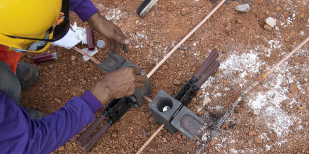
For foundation earth electrodes, the electrical continuity of steelwork in reinforced concrete structures shall be ensured. Steelwork within reinforced concrete structures is electrically continuous if the major parts of vertical and horizontal bars are connected. Connections between metal reinforcement parts shall be either welded, clamped, or overlapped by a minimum of 20 times their diameters and bound by conductive thread or otherwise securely connected. Special care should be exercised at the interconnections to prevent damage to the concrete due to localized arcing across poor contacts.
The minimum radius of the outer earthing ring
The minimum radius of the ring conductor or the foundation earth electrode (re) is 5 meters for a system designed to meet lightning protection Class III or IV. For lightning protection Class I or II, the minimum radius is proportional to soil electrical resistivity (refer to the figure below from IEC 62305-3).

The length of the additional horizontal conductor required is the length of the installed ring conductor (l1) minus its radius (re).
The length of earthing rods should be not less than (l1 – re) / 2, and the quantity should match the number of lightning protection down conductors, with a minimum of two. An additional 0.5 meters should be added to the length should the soil in the region be prone to freezing.
Typical WTG local earthing
The manufacturer-specified earthing and their designs will typically align with IEC 61400-24 guidelines.
Wind turbine manufacturers typically prescribe an earthing system design that exceeds the minimum requirements of IEC 61400-24 (and IEC 62305-3) for added protection and personal safety.
A typical local WTG earthing arrangement is shown in the figure below. There are two separate earthing ring conductors; the inner ring is bonded to the steel reinforcement and the flange plates on the tower structure, whilst the outer ring is installed in the native soil and bonded with the maintenance earth bar inside the tower and bonded with the step-up transformer earth bar.

Soil Electrical Resistivity
The procedure for soil resistivity measurements should follow IEEE Standard 81 guidelines. The probe spacings for Wenner measurements should range from short up to large spacings to measure the shallow and deep resistivity layers. It is important to measure soil resistivity at wide spacings since earth return fault currents are sensitive to the resistivity of deep soil layers over the wind farm site.
For each location, a test engineer should determine the optimal trend for the best-fit curve through the data after considering the localized geology, sources of error, and seasonal variations effects on the data. Then using software, an equivalent and optimal multilayered soil model will be calculated (see image).

Critical locations
Soil electrical resistivity tests are undertaken at separate locations with soil models developed for specific locations across the wind farm. Tests should be undertaken at critical locations that include:
- Main substation.
- Junction box locations.
- Grounding transformer locations (if outside substation).
- WTG locations.
- Switchgear or operational and maintenance buildings (if outside substation).
- Meteorological stations.
If a set of critical locations are near enough to each other and the terrain is similar, then one soil resistivity test could possibly be made for them. Alternatively, a subset of tests may be selected such that it is sufficient to establish a representative set of soil models.
Recommendations
- Perform measurements at critical locations, including at all WTG locations.
- Wenner soil resistivity measurements should be taken at the recommended spacings (see table below) that provide even distribution along the x-axis of a logarithmic soil resistivity plot.
- Measure up to 54 m probe spacing for all WTG locations and above that for the main substation (dependent on the overall size).
- For each location, two measurement traverses at 90 degrees should be performed.
- Ideally, perform measurements during colder weather periods after extended dry (low rainfall) periods to obtain conservative results. Record current weather conditions for the time of the measurements and obtain the rainfall information from some reasonable time back to establish the conservativeness of the measurements.
- If soil conditions were optimistic during testing (warm and high soil moisture content), return to the site to perform a limited set of soil resistivity measurements to help confirm that the earthing system design will be applicable to all conditions.
- Record the driven depth of measurement probes along with readings. The driven depth is used in the software model to account for inaccuracies in the measured fields at short spacings.
- Investigate potential sources of error (i.e., buried metallic objects, nearby parallel transmission lines, cathodic protection systems, or railway traction systems) to identify erroneous data points.

Fault current analysis
All faults considered are single phase-to-earth types. An equivalent impedance model of the entire wind farm earthing is created, and various fault scenarios are analysed. The individual earthing systems, such as the WTGs, are included as a lumped impedance (which needs to be calculated using software).
It is recommended to use software to perform fault current analysis. There are simple equations that exist for approximating the split factors at a WTG (where the split factor is the ratio of the earth fault current in the return path to the total available fault current at the location of the fault).
Data required
To build the model of the wind farm earthing system for fault current analysis, the following data is required.
- Earth fault current level (prospective) at the main substation.
- System (transformer) earthing configuration and neutral grounding (if applicable).
- Feeder cable and/or overhead line data – cable construction and installation configuration, overhead line configuration. ECC and/or earth wire data. For series and mutual impedances.
- Standalone impedances for main substation earthing and for individual WTG earthing systems (calculated using their local soil resistivity models).
- Simplified (and conservative) 1 or 2 soil layer soil resistivity model for the entire wind farm network site. It is best to use the soil resistivity model for the HV substation for fault current analysis because this model incorporates the best approximation of the deep soil layer resistivity.
- Protection clearing times for HV and MV fault scenarios.
Fault scenarios

(1) Transmission line HV fault
(2) Main substation HV fault
This fault scenario can be used for designing and assessing safety at the HV substation.
A fault at the HV substation will usually result in lower voltages at the individual wind turbines than faults directly at the wind turbine locations (and junction boxes) because the individual wind turbines are far away from the substation, but this may not always be the case and needs to be checked.
(3) Collector MV line fault
An MV earth fault in the collector network (overhead line or cable fault) will cause a voltage rise at the fault location, at the substation, and at the wind turbines. The nearer the fault location to the substation or wind turbine earth grids, the higher the voltage rise for that location. However, the voltage rise at the aforementioned locations will be greatly reduced due to most of the fault current returning to the source via the overhead earth wires, earthed cable screens, and earth continuity conductors.
(4) Wind turbine faults
Generally, the fault scenario on the MV side of the step-up transformer will result in the highest voltage rise at WTGs. However, transfer voltages to the earthing systems of WTGs nearer to a fault at the substation (scenario 1) may be more dangerous and needs to be assessed.
The current from a single phase-to-earth fault on the MV side of the step-up transformer at the wind turbine will return to the substation (source) via a split between the earthed cable screens or overhead earth wires, the earth continuity conductors, and the soil (which results in a voltage rise at the wind turbine).
The current from an LV single phase-to-earth fault at the wind turbine will circulate internally within the turbine tower. The voltage rise from this kind of fault should be negligible.
(5) Junction box MV faults
Software Modelling and Assessment
The earthing system modelling comprises two main components:
- An overall wind farm system model that determines the fault current distributions; and
- Models for individual earthing systems, including each WTG, junction box, etc.
EPR hazard zones and overall grid impedance
As a result of the surface voltages, there may be hazardous voltages transferred to nearby assets such as telecommunication or metallic pipeline infrastructure. Hazardous transfer voltages to nearby fences or other conductive infrastructure may also occur and need to be checked.

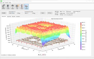
Main substation safety analysis
The example below shows the voltages that occur during an earth fault at a typical wind farm collector substation earthing grid. A safe design is achieved once the calculated touch and step voltages (within the substation and exterior to it) are below the permissible touch voltage limit(s).


Wind turbine earthing safety analysis
The first step is to calculate the local WTG grid impedance using the local soil resistivity model. The WTG grid impedance must be lower than 10 Ω (or a lower value as required by the WTG manufacturer) measured at power frequencies for acceptable lightning performance. The local WTG earthing systems that exceed this limit must be appropriately reinforced per the guidelines of IEC 62305-3.
The final calculated local WTG grid impedances are used for the fault current analysis. The worst-case fault scenario may either be from an MV fault at the WTG or HV substation earth fault and needs to be assessed. The fault scenario with the highest ratio of the resultant WTG foundation current to touch voltage limit (based on the respective fault clearing times) shall be used for assessing GPR, touch, and step voltages.
The safety of each individual WTG is assessed for the following hazard scenarios. A person touching the WTG tower wall while there is simultaneously an earth fault on the MV side of the tower may be subject to touch voltages. Similarly, a person walking in the vicinity of WTG foundations may be subject to step voltage under the same fault conditions. A person touching a given WTG tower or walking by the same given WTG while there is an MV short-circuit to the ground at a nearby WTG may be subjected to transferred voltages.


Junction boxes

WF - Validation Testing
The substation earth grid is tested at the completion of the construction of its earthing system, including after the installation of the electrical switchgear and metallic fences. This is prior to the interconnection of the collector cable circuits (screens) and ECCs of the wind farm. Each WTG earthing system is tested whilst being isolated from the connecting earth conductors.
The validation tests to be performed for both the substation and WTG earthing systems include continuity testing, standalone grid resistance measurement through current injection, and touch and step voltage measurements to confirm safety per the design.
In the future, additional work will be needed to perform fault current splits measurements whilst injecting current to be comparable to the initial validation tests.
References:
[1] IEC 62305-3:2010 Protection against lightning – Part 3: Physical damage to structures and life hazard
[2] IEC 61400-24:2019 Wind Energy Generation Systems – Part 24: Lightning Protection
[3] IEEE Standard 81-2012 IEEE Guide for Measuring Earth Resistivity, Ground Impedance, and Earth Surface Potentials of a Grounding System
[4] IEEE Std 2760-2020 IEEE Guide for Wind Power Plant Grounding System Design for Personnel Safety
[5] IEEE Std 80-2013 – IEEE Guide for Safety in AC Substation Grounding
[6] BS EN 50522:2010 Earthing of power installations exceeding 1 kV a.c.
[7] AS/NZS 2067:2016 Substations and high voltage installations exceeding 1 kV a.c.