Free Calculators
Cable Sizing AS3008 Calculator
Cable Sizing BS7671 Calculator

Voltage Drop Calculator
Arc Flash Calculator

Earth Cable Sizing Calculator

Fault Loop Impedance Calculator
Earth Grid Resistance Calculator

Earth Grid Conductor Sizing
Earthing Rods Resistance Calculator
Lightning Protection Design
Relay Tripping Time Calculator
Equivalent Thermal Resistance
Touch and Step Voltage Calculator
This free electrical calculator determines the safe (permissible) voltage limits for designing electrical earthing and grounding systems.
The calculations comply with IEEE Standard 80.
Your Calculated Safety Criteria Is:
The equations used to calculate touch and step voltages in this calculator are derived from IEEE Standard 80, ensuring full compliance with the standard's guidelines.
**Disclaimer**: Our electrical calculators are intended for use by qualified electrical professionals only. While we strive to provide accurate and up-to-date information, these tools are provided as a guide and should not replace professional judgment or compliance with relevant standards and regulations. Users must verify the results independently and assume full responsibility for their application.
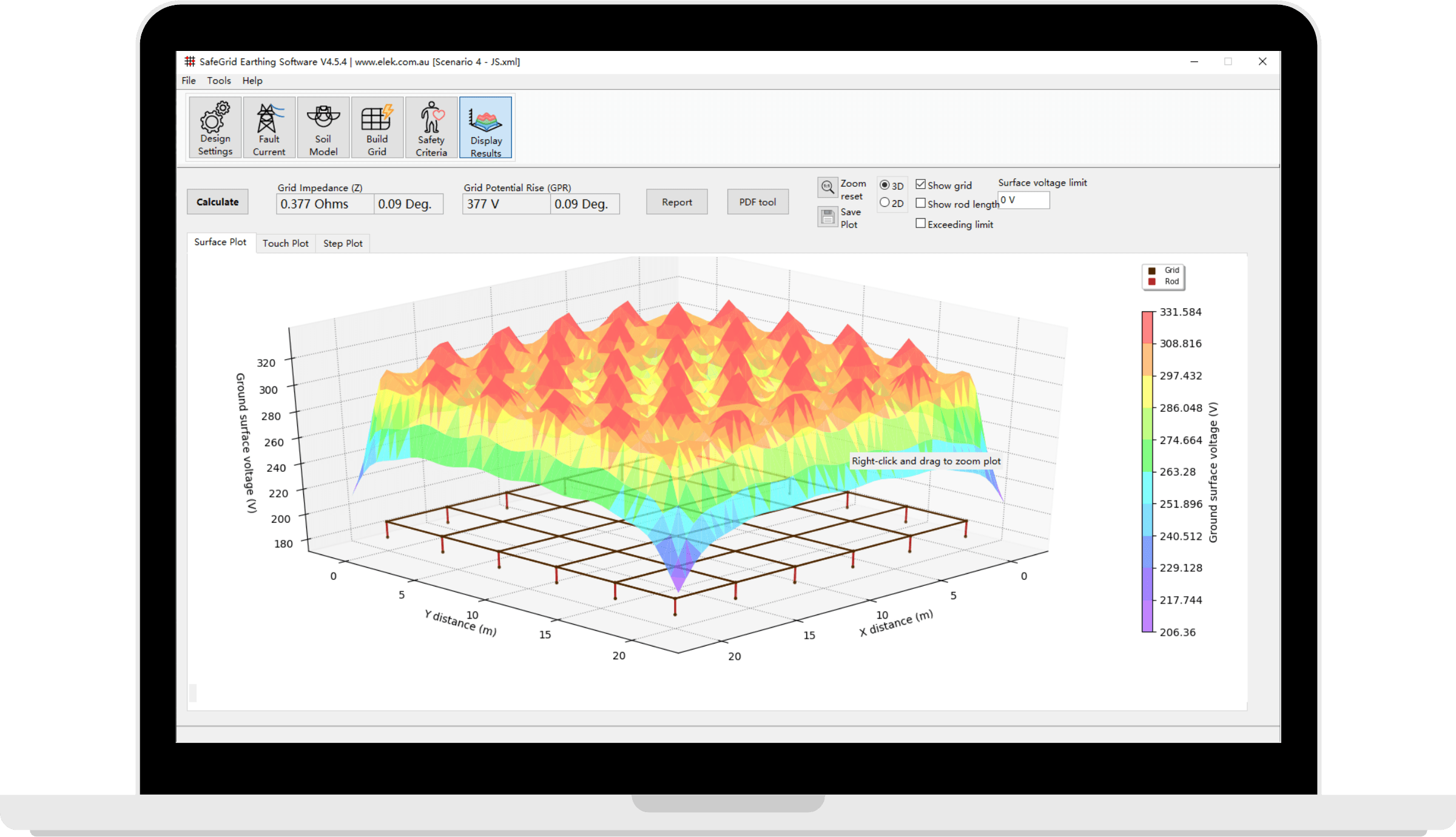
Need Professional Earthing Software?
SafeGrid Earthing Software is comprehensive, accurate and easy-to-use software for modelling earthing systems.
Calculate the grid resistance, grid potential rise (GPR), touch and step voltages of earthing systems of any shape or size.
How to use
Calculator inputs explained
Body weight
- The fibrillation current depends on the body weight (50 kg or 70 kg) and the duration of the fault current.
- Allowable body current which can be survived by 99.5% of persons.
Shock duration (s)
- Duration of the fault current. Refer to the Frequently asked questions below.
- Safety relies on preventing critical shock energy absorption before the fault is cleared and the system is de-energised.
Resistivity of the native soil (Ohm.m)
- This is the electrical resistivity of the native soil.
- If the soil electrical resistivity is not known, a value of 100 Ohm.m is typically assumed.
- For uniform soil this value is the measured resistivity of the soil.
- For multilayered soils it's harder to select this value. Top (shallow) soil layers generally have more effect on touch voltages.
Resistivity surface layer resistivity (Ohm.m)
- For multi-layered soil, thermal resistivity of the soil in the top layer.
- Surface layer material helps in limiting the body current by adding resistance to the equivalent body resistance.
Surface layer depth (m)
- Thickness of the surface soil layer.
- As the surface layer depth increases, the grid's resistance approaches that of a grid in uniform soil with the same resistivity as the upper layer.
Frequently asked questions
How do I calculate safe limits in accordance with European Standards?
- You will need to perform safty calculations in accordance with IEC 60479.
- ELEK SafeGrid Earthing Software can perform safety limit calculations in accordance with European Standards.
What equations does the calculator use and where can I find them?
- The calculator uses equations from IEEE Standard 80-2013.
- The following article contains the equations used for the calculations: Safety Limit Calculations to IEEE and IEC Standards
Should I select 50 kg or 70 kg for body weight?
- According to IEEE Std 80, the choice between using 50 kg or 70 kg body weight for touch voltage limit calculations depends on the specific application and safety requirements.
- When deciding which body weight to use, consider the following factors: Location of the grounding system (public vs. restricted access), likelihood of children being present, local regulations or utility requirements, specific safety policies of the organisation or the electrical utility.
- 50 kg body weight: This is considered the more conservative approach, as it results in lower tolerable touch and step voltage limits. It is typically used for general public areas or locations where children may be present. The 50 kg limit provides a higher safety margin and is often the default choice for many grounding designs.
- 70 kg body weight: This represents an average adult and results in slightly higher tolerable voltage limits. It can be used in areas restricted to adult workers or where public access is limited. The 70 kg limit may be appropriate for industrial settings or utility-only access areas.
What value should I enter for shock duration?
- The value of shock duration can significantly impact the calculated touch voltage limits and the overall grounding system design. It's important to use a value that accurately represents your system's protection scheme while maintaining an appropriate safety margin.
- Fault clearing time: The shock duration is typically set to the fault clearing time of the protective devices. This is the time it takes for circuit breakers or other protective equipment to interrupt the fault current.
- Primary vs. backup protection: IEEE Std 80 allows using either primary or backup fault clearing times. Using backup clearing times will yield more conservative (safer) results.
- Typical range: The general norm for good practice in earth grid design is to have a maximum fault current duration of 0.5 seconds, as stated in IEEE Std 80-2013.
- Common values: Typical shock durations used in calculations range from 0.3 to 0.5 seconds.
- Conservative approach: If you're unsure about the exact clearing time, it's safer to use a longer duration as it will result in more conservative (lower) tolerable touch voltage limits.
- Multiple scenarios: It's often beneficial to calculate touch voltage limits for multiple shock durations to understand how the safety criteria change with different fault clearing times.
- Protective relay settings: Review the actual protective relay settings and historical fault clearing data for your specific system to determine the most appropriate shock duration to use.