What is touch voltage?
There are two main methods of protection against electric shock, the first being termed basic protection which is protection against direct contact of persons or livestock with live electrical parts. The second method of protection is fault protection which is the protection of persons or livestock against contact with exposed conductive parts which were made live during a fault condition.
The touch voltage concept, which is a simple but important safety concept, is concerned with fault protection. The definition of “touch voltages” is those voltages that exist between simultaneously accessible exposed and extraneous conductive parts that may lead to the risk of electric shock in the event of an electrical fault.
The Australian Wiring Rules AS/NZS 3000 defines touch voltage as the voltage appearing between simultaneously accessible parts. The American Standard NFPA 70E defines “touch potential” as a ground potential gradient difference that can cause current flow from hand to hand, hand to foot, or another path, other than foot to foot, through the body. The British Standard BS 7671 does not explicitly refer to “touch voltage” but refers to protection against electric shock.
! Note that just because a piece of electrical equipment is properly earthed that it is not possible to receive an electric shock during a fault. This is completely incorrect.
In a correctly designed electrical installation all exposed conductive parts which may be touched, either directly or indirectly, must be earthed and bonded back to a common earthing point such as the main earth bar. During an earth fault, a touch voltage is developed leading to a risk of shock which is not eliminated through earthing or bonding. It is the purpose of the electrical protection systems during such an earth fault to ensure the fault is disconnected fast enough to ensure the touch voltage created will not be harmful to any person or livestock which is exposed.
Remember the risk of harm to a person from exposure to touch voltages depends on both the voltage magnitude and the duration of exposure (fault clearing time).
Touch voltage limits and disconnection time
The touch voltage safe limits for various electrical standards are listed below but are firstly explained.
Touch voltage limits are derived based on the magnitude and duration of current conducted through a human body at 50 Hz or 60 Hz that can cause ventricular fibrillation of the heart.
In the IEC 60479 standard, the required relationship between prospective touch voltage and disconnection time is described as two curves shown in Figure 1 where the L-curve is for normal conditions (dry with a floor presenting significant impedance) and Lp-curve is for wet conditions.

Therefore, within the context of an electrical installation the touch voltage limits depend upon the disconnection time of a fault. Figure 1 shows that the disconnection time can be 5 seconds or longer when the touch voltage is 50 V (for dry conditions).
The Australian Standard AS/NZS 3000:2018 considers that for most final sub-circuits, the prospective touch voltage limit is around 92 V (Refer to Section 3.2.1 of that standard for details). This touch voltage approximates to a time of 0.4 s according to the curve L in Figure 1. Therefore, for hand-held equipment, the maximum disconnection time for a 230 V AC to earth should not exceed 0.4 s. Furthermore, the limit of 50 V corresponds to 0.5 s according to the curve L in Figure 1. Therefore, maximum disconnection time of 5 s is permitted for circuits not directly supplying portable or hand-held equipment. A summary of touch voltage limits for this standard is below in the table.
Table 1. Touch voltage limits per AS/NZS 3000
| Current | Conditions | Disconnection time | Touch voltage limit |
| AC | Normal (dry) | < 0.4 s | 100 V |
| AC | Normal (dry) | 0.4 s ≤ t ≤ 5 s | 50 V |
| AC | Wet | < 0.4 s | 25 V |
| AC | Wet | 0.4 s ≤ t ≤ 5 s | 55 V |
| AC | - | ≤ 5 s | 120 V |
The American Standards NFPA 70E for workplace safety also considers 50V or greater as a hazardous touch voltage. It is important to note that 70E applies the 50V maximum to both alternating current (AC) and DC.
The British Standard BS 7671 does not explicitly mention touch voltage but provides maximum disconnection time limits for “protection against electric shock”. The table below lists the maximum disconnection times for final sub-circuits per section 411.3.2.2 – note that disconnection time reduces with increasing supply voltages. For other distribution circuits (lower probability of touch compared with final sub-circuits) a maximum disconnection time of 5 s is allowed.
Table 2. Maximum disconnection timesof final subcircuits for TN systems per BS 7671
| 50 V <U° ≤ 120 V | 120 V <U° ≤ 230 V | 230 V <U° ≤ 400 V | U°>400V | ||||
| AC | DC | AC | DC | AC | DC | AC | DC |
| 0.8 s | - | 0.4s | 0.1s | 0.2 s | 0.4 s | 0.1s | 0.1s |
| 0.3 s | - | 0.2 s | 0.4 s | 0.7 s | 0.2 s | 0.4 s | 0.1 s |
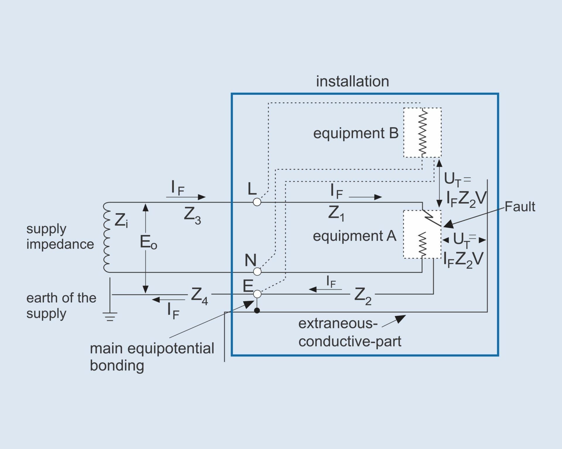
Touch voltage calculation
Where If is the earth fault current,
Eo is the induced emf (to earth of the source) in V
Zi is the internal impedance of the source in Ω
Z1 is the impedance of circuit phase conductor in Ω
Z2 is the impedance of circuit protective(earth) conductor in Ω
Z3 is the impedance of external phase conductor in Ω
Z4 is the impedance of external circuit protective(earth) conductor in Ω
 (Eq. 2)
This is a simplified equation to calculate the touch voltage that is derived as follows from the equation (1). The following shows how to obtain the basic touch voltage equation.
As Zi + Z3 + Z4= ZE is the external impedance of earth fault loop, the equation (1) becomes:

Again, for conductors of cross-sectional area not exceeding 35 mm2, if the phase and protective conductors of a circuit are of the same material and are run over the same route:

Where A1 is the cross-sectional area of the phase conductor in mm2
A2 is the cross-sectional area of the protective conductor in mm2
The equation then becomes:

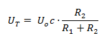
This equation is also in accordance with the Clause B4.3 of AS/NZS 3000:2018 [1] it is stated:
- The factor c: represents the proportion of the supply voltage available at the reference point during operation of the protective device.
- The value m: is the ratio of the cross-sectional area of the phase conductor compared to the cross-sectional area of the protective earthing conductor in the circuit considered.
Typical prospective touch voltage for most final sub-circuits
For most final sub-circuits, 0.8 for the factor c and a ratio m of 1 can be used. Therefore:

This touch voltage approximates to a time of 0.4 s according to the curve L (for normal conditions) in Figure 1 above.
References:
[1] AS/NZS 3000:2018 Wiring Rules.
[2] NFPA 70E:2021 Standard for Electrical Safety in the Workplace.
[3] BS 7671 – 18th Edition – IET Wiring Regulations.
[4] IEC 60479 – Effects of current on human beings and livestock.