Table of Contents
Introduction
The normal use of cable sizing standards is to select a conductor size of minimum cross-sectional area ensuring safe operation and minimum initial cost of the cable. The problem with this approach is it fails to consider important economic and environmental factors. Economic cable sizing also includes the cost of electrical losses, which are often significant, over the lifetime of the cable.
The Standard IEC 60287-3-2 [ref. 1] discusses the economic sizing calculations in detail. The losses decrease as conductor size increases therefore for a significant number of cases a larger size of conductor than would be chosen based on the minimum initial cost of purchase alone will lead to lower power loss which will be much less expensive over the operating lifetime of the cable. An economically sized cable will always be larger than that based on safety factors and cable costs alone. For a typical example given in IEC 60287-3-2, the saving in the combined cost of purchase and operation is of the order of 50 % [ref. 1].
The low voltage cable sizing Standard AS/NZS 3008.1 [ref. 2] provides a method for economic cable sizing based on the IEC standard. The equations and the examples described herein are based on the approach shown in this Standard.
The steps for determining an economic cable size are:
- Calculate minimum cable size by applying safety-based rules such as current-carrying capacity, voltage drop requirements, and short-circuit rating.
- Choose a set of larger cable sizes above the minimum size based on safety.
- Determine the total upfront costs for all cable sizes which includes the cable procurement costs, logistics, and the laying costs.
- Calculate the losses and cost of losses for all cables.
- Calculate the savings (in net present value) due to the reduced losses for the larger cables.
- Find the total savings (in net present value) considering the upfront and the losses for the larger cables.
The larger cables having a benefit-to-cost ratio greater than unity would offer lifetime benefits. Of these cables, the cable that gives the highest total savings (in net present value) is selected and is the economic cable size to be used.
Mathematical Formulation
A. Calculation of cable a.c. resistance
The a.c. resistance of cables affects the calculation of the losses. Resistance depends on cable operating temperature, which depends on the operating current.
For the determined size of conductor, the operating current is
\(I_0=\ I_l\ast U.F.\)
where is the operating current, is the maximum demand and is the percentage utility factor. The conductor temperature () is estimated from the below equation
\(\left(\frac{I_0}{I_r}\right)^2=\ \frac{\theta_0-\theta_A}{\theta_R-\theta_A}\)
where \(θ_0[\) is the cable operating temperature, \(θ_A\) is the ambient temperature, \(θ_R\) is the temperature when the cable carries the rated current \(I_R\).
The calculated temperature is used to determine the conductor resistance from relevant tables for the length of cable run.
B. Cost of I2R losses
The losses for the cables can be calculated from the equation
\(W=\ \left\{\begin{matrix}3I_0^2R_0/1000&3\ phase\ (balanced)\ circuits\\2I_0^2R_0/1000&1\ phase\ circuits\\\end{matrix}\right.\)
where \(R_0\) is the resistance at the operating current \(I_0\). If the unit cost of electricity is p $/kWh the cost of losses per year, C is given by
\(C=\frac{W\ast365\ast24\ast\sum_{i=1}^{n}p_i}{n}\)
C. Net Present Value (NPV)
The net present value of the total cost, \({NPV}_{total}\) is the difference between the net present value of savings in the cost of I2R loss over the time period \({NPV}_{sav}\) and the increase in upfront costs, \(cc\)
\({NPV}_{total}={NPV}_{sav}-cc\)
The net present value of savings in the cost of I2R loss over the time period is given by
\({NPV}_{sav}=\frac{Y\ (1-\left(1+r\right)^{-n})}{r}\)
where is the time period the entity that pays the capital costs accrues benefits from the savings due to the selection of a larger cable size in years.
For a domestic situation this time period is the average time first home buyers stay in the home (~7 years). An appropriate time period should be used for commercial installations (for example 20 years). is the savings in cost of I2R loss in $ and is the discount rate or expected rate of return that those paying for the energy losses could earn for a similar risk in financial markets, in %.
D. Payback period
The payback period, represents the number of years that the accumulated savings of reduced losses equals the additional cost of installing a larger cable size. The payback period is the time period , that makes the net present value of the total cost to be zero.
\(N=\frac{-\log(1-\frac{r\times cc}{y})}{\log(1+r)}\)
Note if electricity costs are increasing then the payback period will be slightly reduced.
E. Benefit to cost ratio
The benefit to cost ratio is the ratio of the \({NPV}_{total}\) to the increase in upfront costs, \(cc\).
\(BC\ Ratio=\ \frac{{NPV}_{total}}{cc}\)
Calculation Results
Two example calculations of economic cable sizing are given for single and multiple circuits of single-core low-voltage cables arranged in different buried configurations. The resistance of cables was determined using ELEK Cable Pro™ software [ref. 3].
The assumptions are as follows:
- The cost of electricity is constant over the cable lifetime.
- The load is considered constant over the cable lifetime.
- The discount rate is considered constant.
A. Example 1 – 3 single core cables carrying 200 A
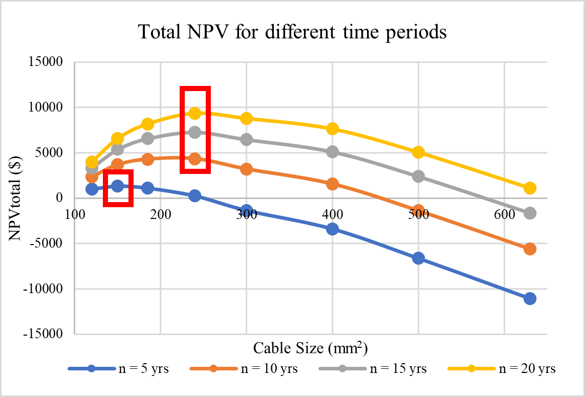
A simulation was performed for three single-core cables that carry a full-load current of 200 A per phase with an 80 % utility factor. The installation has a route length of 100 m and the ambient air temperature is 40 °C. The minimum cable size calculated by Cable Pro™ software was 95 mm2. With a discount rate of 7 % and a 15 cents/kWh electricity charge, the 240 mm2 cable was found to be the economical size with a cost of $9354 and a payback period of 3 years, 10 months, and 5 days.
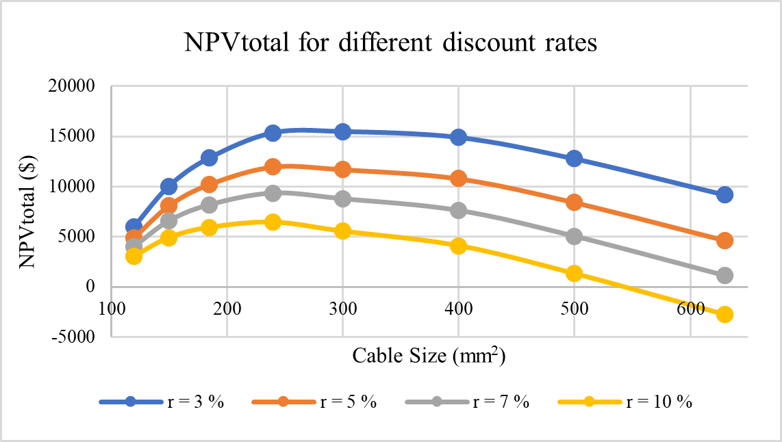
The economic size is highly dependent on the discount rate, the upfront costs, and the period. Fig. 1 shows the variation of the \({NPV}_{total}\) for different periods and Fig. 2 shows the variation of \({NPV}_{total}\) for different discount rates. As the period increases the inflection point shifts and hence larger cables can be considered as the economic cable size.
B. Example 2 – Six motor cables
Six four-core low voltage PVC (V-75) insulated and sheathed copper cables are arranged touching in a single horizontal row on a perforated cable tray for the supply of six identical 22 kW motors which have a full-load current of 45 A per phase and are installed at distances of 40 m, 55 m, 90 m, 135 m, 180 m and 225 m from the origin of the cable tray. The minimum conductor sizes for the six cables as calculated by Cable Pro software are 16 mm2, 16 mm2, 16 mm2, 25 mm2, 35 mm2, and 50 mm2. For 20 years, the discount rate was fixed at 7% and the electricity price was 15 cents/kWh. Table 1 below summarizes the results.
| Section | Minimum Size | Economical Size | NPVtotal | B.C Ratio | Payback Period |
|---|---|---|---|---|---|
| 1 | 16 mm2 | 70 mm2 | $2811.568 | 3.76 | 2 y 6 m |
| 2 | 16 mm2 | 70 mm2 | $3868.02 | 3.75 | 2 y 6 m |
| 3 | 16 mm2 | 70 mm2 | $4501.28 | 3.74 | 2 y 6 m |
| 4 | 25 mm2 | 70 mm2 | $3913.31 | 1.86 | 4y 5m 5d |
| 5 | 35 mm2 | 70 mm2 | $2209.24 | 1.01 | 6y 9m 14d |
| 6 | 50 mm2 | 50 mm2 | - | - | - |
The results show that for sections 1 to 5 an increase in cable size to 70 mm2 will be economical. But for section 6, the minimum cable size is the most economical cable.
Conclusion
The results indicate that the economic sizing of cables leads to economic benefits within the lifetime of the cable. The initial cost of the larger cable will be paid back by the savings in cost of the losses over the life of the cable.
It is recommended to size cables based on economic considerations.
References
[1] IEC 60287, “Electric cables Calculation of the current rating, Part 3-2.” (1995).
[2] AS/NZS 3008.1.1:2017: Electrical installations – Selection of cables, Part 1.1: Cables for alternating voltages up to and including 0.6/1 kV—Typical Australian installation conditions