Table of Contents
Why Install Cables Inside Conduits?
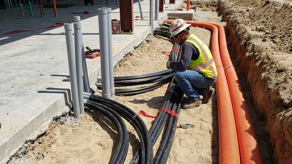
In modern electrical installations, the use of conduits to encase cables offers numerous benefits over direct cable installations. The main reasons for installing cables inside conduits are as follows:
- Protection against mechanical damage reducing the risk of electrical faults and cable failures.
- Protection from environmental factors such as moisture, dust, chemicals, and solar radiation.
- Ease of maintenance and cable replacement.
- Additional fire protection.
- Enhanced electrical installation.
- Cable management and organization.
- Compliance with regulations and standards.
- Use of single-core conductors instead of multicore cables
How to Caculate Conduit Size
This technical reference article provides electrical engineers with a comprehensive guide to conduit sizing calculations. Two practical methods for conduit sizing calculations are presented.
Calculation Method 1 – Calculate the minimum conduit size required for a specific number of cables. This is particularly useful when planning an installation. (Equation 1 below)
Calculation Method 2 – Calculate the maximum number of cables that can be installed in a conduit of a known size. (Equation 2 below)
Further, the reasons for using conduits in electrical installations and the selection of space factor are discussed, concluding with detailed examples of conduit size calculations. By understanding these concepts, electrical engineers can ensure efficient and compliant conduit installations in their projects. We explain conduit sizing according to AS/NZS 3000, BS 7671, and NEC Standards.
ELEK Cable Pro Web Software™ performs automatic conduit sizing.
Space Factor Inside Conduits
Electrical installation standards define maximum conduit fill ratios to ensure safety and functionality. Compliance with these standards, which include space factor requirements, is critical.
Space factor is the ratio of the space occupied by the cables to the total space inside the conduit. Adequate space factor ensures proper airflow in the conduits which helps in the cooling of cables and prevents damages while performing cable pulling operations. Space factor is used for calculating the free space required in the conduits.
Space factors are specified in the standards as follows.
AS/NZS 3000 standard
Section C6 (2018) in Appendix C of the AS/NZS 3000 standard mentions the space factors to be considered subject to limitations as per Figure 1.
- For one cable in enclosure, space factor = 0.5
- For two cables in enclosure, space factor = 0.33
- For three or more cables in enclosure, space factor = 0.4

NEC Standard
Table 1 in Chapter 9 of the NEC standard provides information on how much percentage of the inner conduit area should be filled up be cables as shown in the table below.
Table 1: Recommended Percentage area of the conduit that can be utilized according to NEC
| No of cables | Percentage area of the conduit that can be utilized. |
|---|---|
| 1 | 53 |
| 2 | 31 |
| Over 2 | 40 |
Table 1 of Chapter 9 is based on common conditions of proper cabling and alignment of conductors. For certain conditions, a larger size conduit or lower conduit fill should be considered.
For 3 or more conductors, if the ratio of the raceway inside diameter to the conductor or cable outside diameter is between 2.8 and 3.2, considerable probability of jamming can occur (much lower probability for other ratios).
The maximum number of permitted bends in any one conduit run (in between boxes, conduit body or enclosure) is limited to 360°.
“There shall not be more than the equivalent of four quarter bends (360 degrees total) between pull points, for example, conduit bodies and boxes.”
If the maximum number of conductors or cables (of same size) calculated has a decimal greater than 0.8, the higher whole number may be considered. Similarly, while sizing a conduit for a single conductor, if the calculation is greater than 0.8 decimal, there is no need to consider a higher conduit size.
Note: In communication where the sheaths are weaker than the power cable, certain manufacturers recommend reducing the fill factor in conduits by 15 % for each additional bend over two bends.
BS 7671 Standard
IEE On-site guide BS 7671:2018 provides the cable factors for single-core thermoplastic (PVC) cables for conduit lengths less than and greater than 3 m in length. The cable factors of cables to be routed in a conduit are added up and compared with the conduit factor.
The conduit size that corresponds with the conduit factor greater than or equal to the sum of cable factors is the minimum conduit size required. For example, for laying 4 cables of 10 mm2 cross-sectional area for 3 m length, the sum of cable factors = 4*146 (from Table 2) = 584. From Table 3, the conduit factor greater than the sum of cable factors is 800. Hence, minimum conduit size of 25 mm diameter is required to lay 4 nos. of 10 mm2 cables for 3 m length. The IEE On-site guide also provides cable factors for lay lengths greater than 3m or and for cables incorporating bends or sets as shown in Table 4.
Table 2: Cable factors for use in conduit in short straight runs
| Type of conductor | Conductor cross-sectional area (mm2) | Cable factor |
|---|---|---|
| Solid | 1 | 22 |
| 1.5 | 27 | |
| 2.5 | 39 | |
| Stranded | 1.5 | 31 |
| 2.5 | 43 | |
| 4 | 58 | |
| 6 | 88 | |
| 10 | 146 | |
| 16 | 202 | |
| 25 | 385 |
Table 3: Conduit factors for use in short straight runs
| Conduit diameter (mm) | Conduit factor |
|---|---|
| 16 | 290 |
| 20 | 460 |
| 25 | 800 |
| 32 | 1400 |
| 38 | 1900 |
| 50 | 3500 |
| 63 | 5600 |
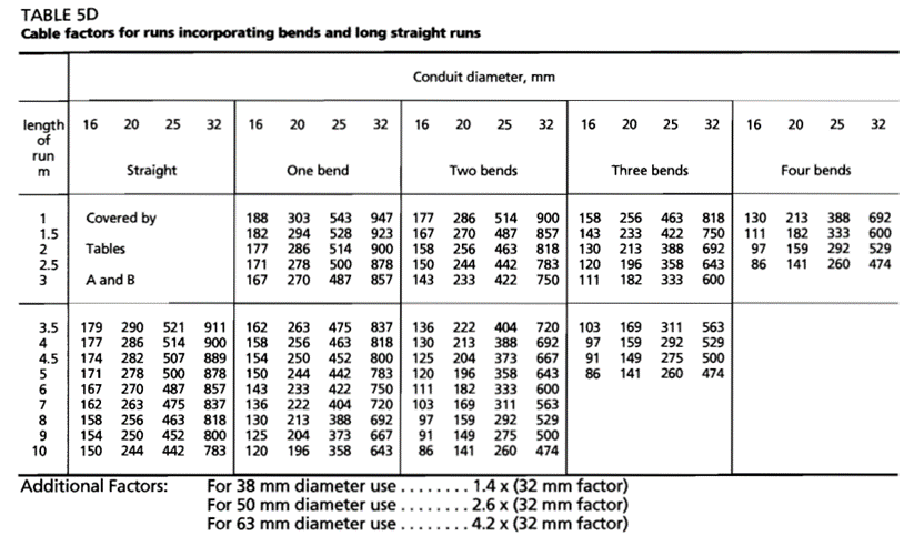
Table 4: Cable factors for use in long straight runs over 3 m or runs of any length incorporating bends
| Type of conductor | Conductor cross-sectional area (mm2) | Cable factor |
|---|---|---|
| Solid or Stranded | 1 | 16 |
| 1.5 | 22 | |
| 2.5 | 30 | |
| 4 | 43 | |
| 6 | 58 | |
| 10 | 105 | |
| 16 | 145 | |
| 25 | 217 |
Further, the cable factors are added together and compared with the conduit factors for cable runs incorporating bends and straight runs of length greater than 3m as shown in Figure 2.
Equations for Conduit Sizing Calculations
Method 1: Determining the conduit size required for a specific number of cables
When we know the number of cables and the area of a single cable (assuming all cables are of a single type), the minimum duct diameter can be calculated using the formula:
\(D=\sqrt{\frac{4\times A \times n}{\pi \times \ sf}}\) [Equation 1]
where:
D is the minimum internal diameter of the conduit required in mm
n is the number of cables
sf is the space factor.
A = π(d/2)2 is the area of a single cable in mm2, and
d is the overall diameter of a single cable in mm.
Refer to calculation example 1 for a practical example of its application.
Method 2: Determining the maximum number of cables that can be installed in a conduit of a specific size
When we know the conduit internal diameter size and the area of the cable to used, the maximum number of cables (assuming all cables are of a single type) can be calculated by the formula,
\(n=\frac{\pi \times D^2 \times sf}{4 \times A}\) [Equation 2]
Refer to calculation example 2 for a practical example of its application.
Example Calculations
Example 1 - Number of cables is known
Determine the conduit size required for installing two 70 mm2 XLPE or Elastomer (90 degree Celsius), 0.6/1kV single core copper cable. Base the space factor on requirements from AS/NZS 3000.
Step 1. Calculate the area of one cable
The diameter of the cable from the manufacturer datasheet is 14.7 mm.

Calculate the area of the cable:
\(\begin{aligned}
A=\pi \times \left(\frac{d}{2}\right)^2
\\
A=\pi \times \left(\frac{14.7}{2}\right)^2
\end{aligned}\)
Hence the cross-sectional area of a cable = 169.71 mm2.
Step 2. Obtain the space factor
From the section above, the space factor for 2 cables is 0.33.
Step 3. Calculate the minimum conduit inner diameter
From equation 1 above:
\(\begin{aligned}
D=\sqrt {\frac{4 \times A \times n}{\pi \times sf}}
\\
D=\sqrt {\frac{4 \times 169.71 \times 2}{\pi \times 0.33}} = 36.188 mm
\end{aligned}
\)
The next available standard conduit of inner diameter 40 mm is the minimum required conduit size for installing the two 70 mm2 cables.
Example 2 - Conduit size is known
Determine the number of 500 mm2 XLPE or Elastomer (90 degree Celsius), 0.6/1kV single core copper cable that can be installed in a 125 mm (ID) conduit. Base the space factor on requirements from AS/NZS 3000.
Step 1. Calculate the area of one cable
The diameter of the cable from the manufacturer datasheet is 14.7 mm.

Calculate the area of the cable:
\(\begin{aligned}
A=\pi \times \left(\frac{d}{2}\right)^2
\\
A=\pi\times\left(\frac{37}{2}\right)^2
\end{aligned}
\)
Hence the cross-sectional area of the cable = 1075.21 mm2.
Step 2. Obtain the space factor
We need to guess the space factor at first. We assume that there will be more than three cables installed inside the conduit so a space factor of 0.4 is used.
Step 3. Calculate the maximum number of cables by using Equation 2.
\(\begin{aligned}
n=\frac{\pi\times D^2 \times sf}{4 \times A}
\\
n=\frac{\pi \times 125^2 \times 0.4}{4 \times 1075.21} = 4.5653 = 4
\end{aligned}
\)
Hence the maximum number of 500 mm2 cables that can be installed in 125 mm conduit is 4. The calculated cable number should be rounded down to the closest integer value to meet the conduit fill requirements.
Conclusions
This technical reference article provides electrical engineers with a comprehensive guide to conduit sizing calculations while referring to standards such as AS/NZS 3000, NEC, and BS 7671. Accurate conduit sizing is essential for the safety, efficiency, and compliance of modern electrical installations.
A suitable space factor in conduit sizing ensures proper airflow, cable cooling, and the prevention of damages during cable pulling operations. While standards dictated maximum fills are to be respected, the pulling tension, jam ratio and other factors govern the number of conductors being installed when considering long runs (typically underground) and/or multiple bends. Nevertheless, for shorter runs, those limits are enough. Where available, the cable manufacturer recommendation will govern the installation. While the fill ratios is important, they are not complete. A cable pulling tension calculation may be essential to ensure cables can be pulled into the conduits, especially for underground installations.
References
[1] Electrical installations “Wiring Rules” (AS/NZS 3000:2018), Appendix C.
[2] National Electric Code (NEC), Chapter 9
[3] On-Site Guide, BS 7671:2018, IEE Wiring Regulations
[4] TheHandbook 2012 EDITION. (2012). Nexans