The calculation of current ratings for groups of (multiple) cable circuits require the quantification of the mutual heating component between the groups of circuits. This example will examine an installation of a multiple groups of circuits in air on the same cable ladder.
This article will discuss the IEC 60287 approach to solving the problem, as opposed to the finite element method which is another way.
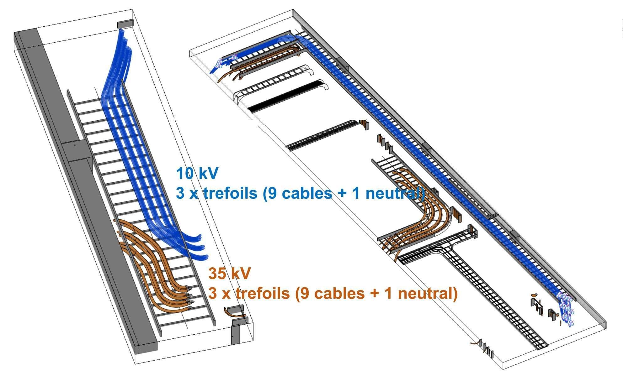
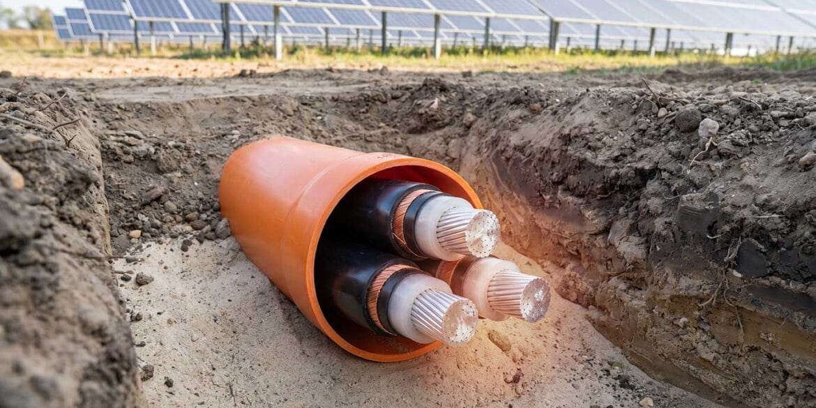
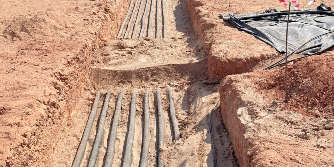
Figure 1. Medium voltage cable circuits installed on the same cable ladder
For multiple buried circuits this is relatively simple exercise to determine the mutual heating since conduction of heat flux through the soil is the only mechanism of heat transfer and so the superposition theorem can be assumed according to IEC 60287-2-1.
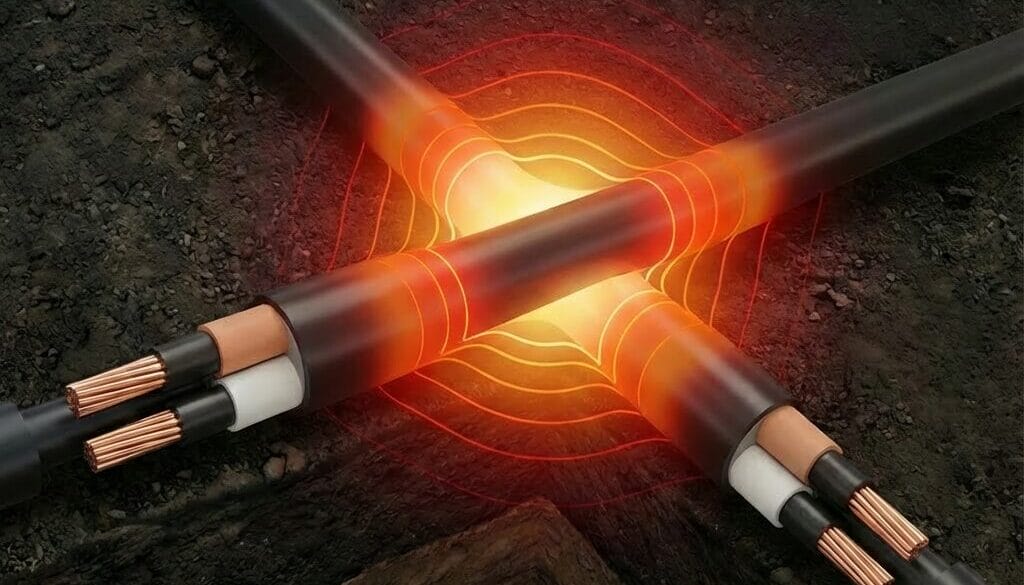
For multiple circuits in air the mutual heating effects are more complicated since they consist of both convection and radiation heat transfer mechanisms. For groups of circuits in air of the same cable type, with the same losses (i.e. carrying the same currents) and neglecting dielectric losses (for XLPE insulated cables dielectric losses can only be neglected below 63.5 kV) we can refer to Standard IEC 60287-2-2 for guidance.
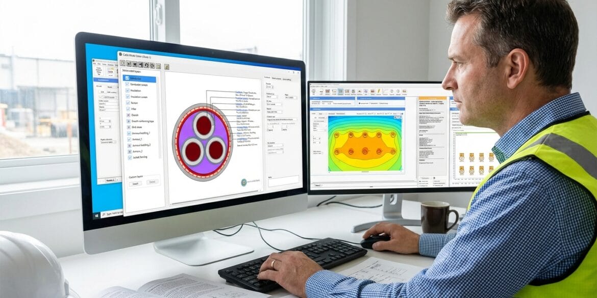
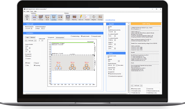
Standard IEC 60287-2-2 provides 12 standard (fixed) configurations for calculation of current rating of groups of cables (of the same cable type) in air. These configurations are provided in the In Groups module of Cable HV™ Software (image below). The reason there are only fixed configurations available is because the method in this standard was developed based on physical experiments which was limited to a study of only these 12 configurations.
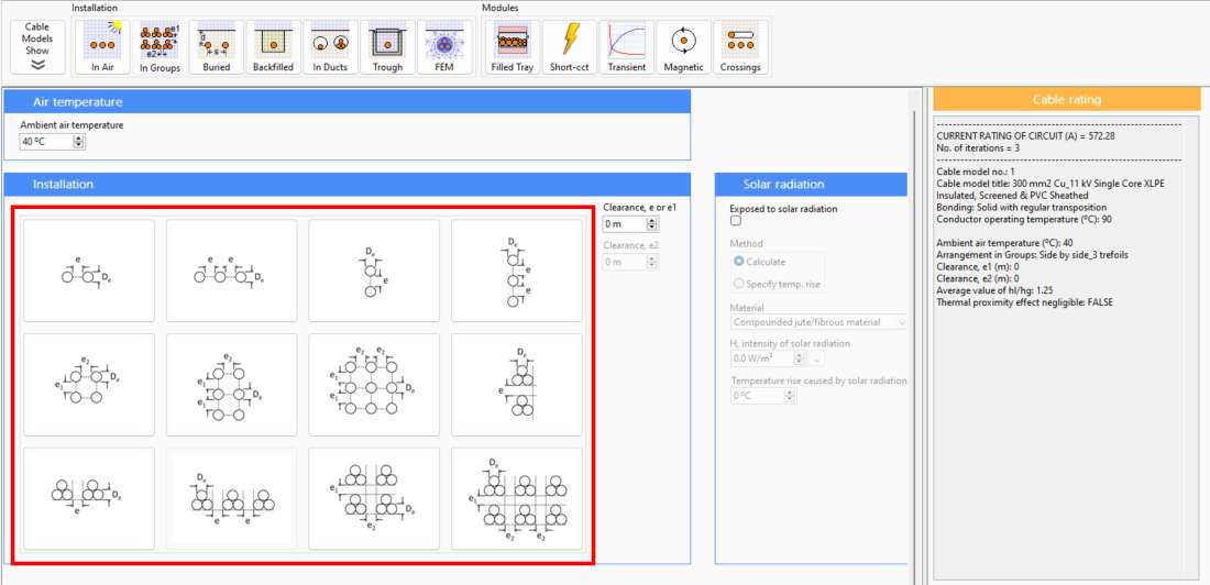
Figure 2. Cable HV™ Software – In Groups module based on IEC 60287-2-2 (for same cable types)
What do we do when there are multiple groups of different cable types?
Well, we can still take guidance from IEC 60287-2-2.
Firstly, we should work out the current rating for the 10 kV and the 35 kV groups of circuits separately using the standard configurations in the software for the same cable types.
Note that if the spacing between the circuits of the 10 kV or 35 kV side-by-side trefoil groups is more than 1.5 times the respective cable diameters (refer to Table 1 from IEC 60287-2-2 below) then the mutual heating between the circuits will be negligible and in fact this means each circuit will have the same current rating as a single isolated circuit in air. We will take advantage of this phenomena when we look at the mutual heating between the groups of different voltages.
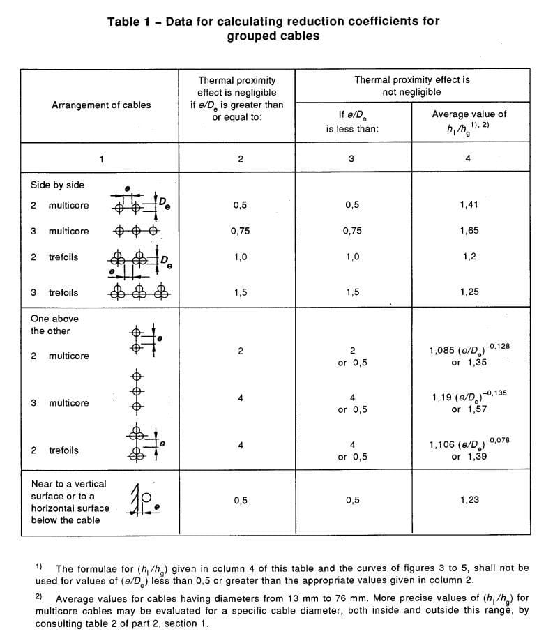
Figure 3. Thermal proximity effects for groups of circuits installed in air [ref. 2]
Referring to Column 2 of Table 1 above from IEC 60287-2-2 this provides the minimum spacing to avoid mutual heating effects for certain configurations of the same cable type. For example, for 3 side by side trefoil circuits when the spacing between the circuits is greater than or equal to 1.5 times the cable diameter then mutual heating is negligible.
In the example shown in Figure 1 it is best to avoid the mutual heating between the 10 kV and 35 kV groups of cables and to ensure there is more than adequate separation between them. We would suggest that with reference to Table 1 below, the separation distance should be at least 3 times the diameter of the largest cable size from both groups. In this example this looks like this amount of separation should be physically viable. If it is not then another multi-step approach using the software is also possible – get in touch if you would like to discuss.
References
“IEC 60287-2-1” Calculation of the current rating – Part 2-1: Thermal resistance – Calculation of thermal resistance.
- “IEC 60287-2-2” Calculation of the current rating – Part 2-2: Thermal resistance – A method for calculating reduction factors for groups of cables in free air, protected from solar radiation.