Table of Contents
Overview: IEC 60287 Limitations and New Soil Drying Methods
This article introduces new methods for calculating power cable current ratings in soil drying scenarios that address IEC 60287 standard limitations.
The limitations of the IEC 60287 standard for dealing with partial soil drying out (that utilizes a two-zone model) include:
It can only be applied to single, isolated cables or circuits.
It can only be applied to cables operating at a unity load factor.
It applies only to direct buried at standard burial depths.
New advanced calculation methods that extend to complex installations with multiple buried circuits, non-unity load factors, and backfilled installations and accurately account for soil drying and moisture migration effects on cable ampacity have been developed by ELEK Software.
A case study is presented to demonstrate the practical application and effectiveness of the advanced calculation methods. The testing results will show how the circuit’s current rating is influenced by the load factor, soil drying out, and backfill protection simultaneosly.
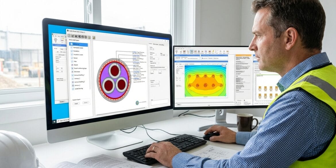
The calculations are performed using ELEK Cable High Voltage™ Software.
Thermal Dynamics of Buried Cables: Soil Drying and Moisture Migration Explained
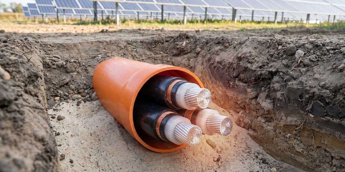
Conductor temperature is a primary constraint in calculating cable ampacity. For underground power cables, soil acts as the principal medium for heat dissipation. The thermal resistance of the soil heavily depends on its moisture content.
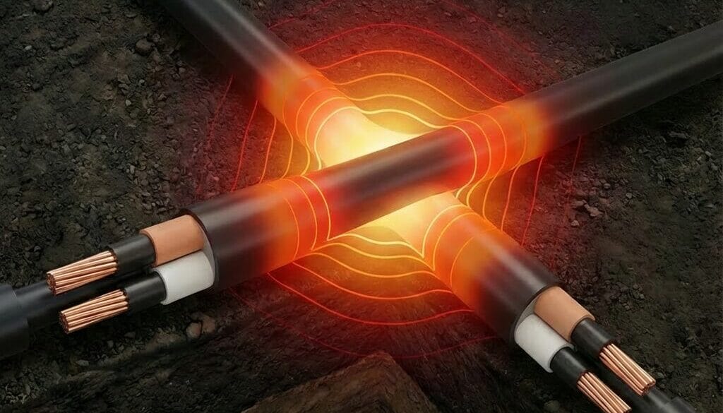
Soil drying out refers to the process where heat generated by buried power cables causes a temperature gradient in the surrounding soil which in turn causes moisture to migrate away from the cable surface. This creates a dry soil zone around the cables which has increased thermal resistivity.
The increased thermal resistivity of the dry soil around the cables reduces the heat dissipation ability of the cables, which can lead to further temperature increases in the cables, potentially reducing their current-carrying capacity.
This process is dynamic and continues as long as there is a temperature difference between the cable surface and the surrounding soil.
Understanding these phenomena is crucial for accurately calculating cable ampacity and designing cable installations to account for the effects of soil drying on heat dissipation and cable performance.
The IEC 60287 Calculation for Buried Cables with Soil Drying
The standard IEC 60287-1-1 [1] provides a method for calculating the steady-state current rating of cables that are direct buried in soils experiencing partial drying. The IEC method utilises a two-zone model: one zone direct around the cable that has dried out and another that maintains the original thermal resistivity of the site. An isotherm defines the boundary between these two zones.
The IEC method suggests that the ratio of the thermal resistivity of the dried-out soil and the native soil (\(\nu\)) should increase the cable or circuit’s external thermal resistance. It also suggests an increase in the temperature rise proportional to the rise in temperature required to induce soil dry-out (\(\Delta \theta_x\)). These changes are incorporated into the current rating equation as below.
\(I = \left[\frac{\Delta \theta – W_d [0.5T_1 + n(T_2 + T_3 + vT_4)] + (v – 1)\Delta \theta_x}{R[T_1 + n(1 + \lambda_1)T_2 + n(1 + \lambda_1 + \lambda_2)(T_3 + vT_4)]}\right]^{0.5}\)
where
\(\nu = \frac{\rho_d}{\rho_s}\) : is the ratio of the thermal resistivities of the dry and moist soil zones;
\(R\) : is the AC resistance of the conductor at its maximum operating temperature (\(\Omega/m\));
\(\rho_d\) : is the thermal resistivity of the dry soil (\(K \cdot m/W\));
\(\rho_s\) : is the thermal resistivity of the native soil (\(K \cdot m/W\));
\(\theta_x\) : is the critical temperature of the soil and temperature of the boundary between dry and moist zones (\(°C\));
\(\theta_a\) : is the ambient temperature (\(°C\));
\(\Delta \theta_x\) : is the critical temperature rise of the soil. This is the temperature rise of the boundary between dry and moist zones above the ambient temperature of the soil \(\theta_x – \theta_a\) (\(K\));
The IEC standard method is appropriate for scenarios where a basic understanding of soil behavior around cables is sufficient.
Advanced Calculations Beyond IEC 60287 Capabilities
Accurate ampacity ratings for real-world buried cable installations require advanced calculation methods beyond IEC 60287’s capabilities. The standard’s simplified approach overlooks critical factors affecting underground cable temperatures, such as:
Soil drying in multiple buried circuits
Soil drying in backfilled circuits
Varying load factors with or without soil drying
Unrestricted backfill dimensions
ELEK Software has developed advanced calculation solutions for these complex issues, incorporating them into its software to provide more precise ampacity calculations for buried cables.
Case Studies: Multiple Buried Circuits with Soil Dry-out
The following example calculations demonstrate how engineers can now investigate the influence of soil drying out, load factor, and backfill dryout protection on the ampacity ratings of buried cable installations simultaneously.
Installation Conditions
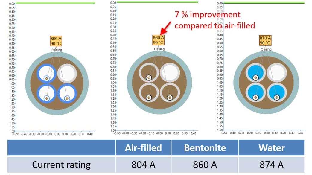
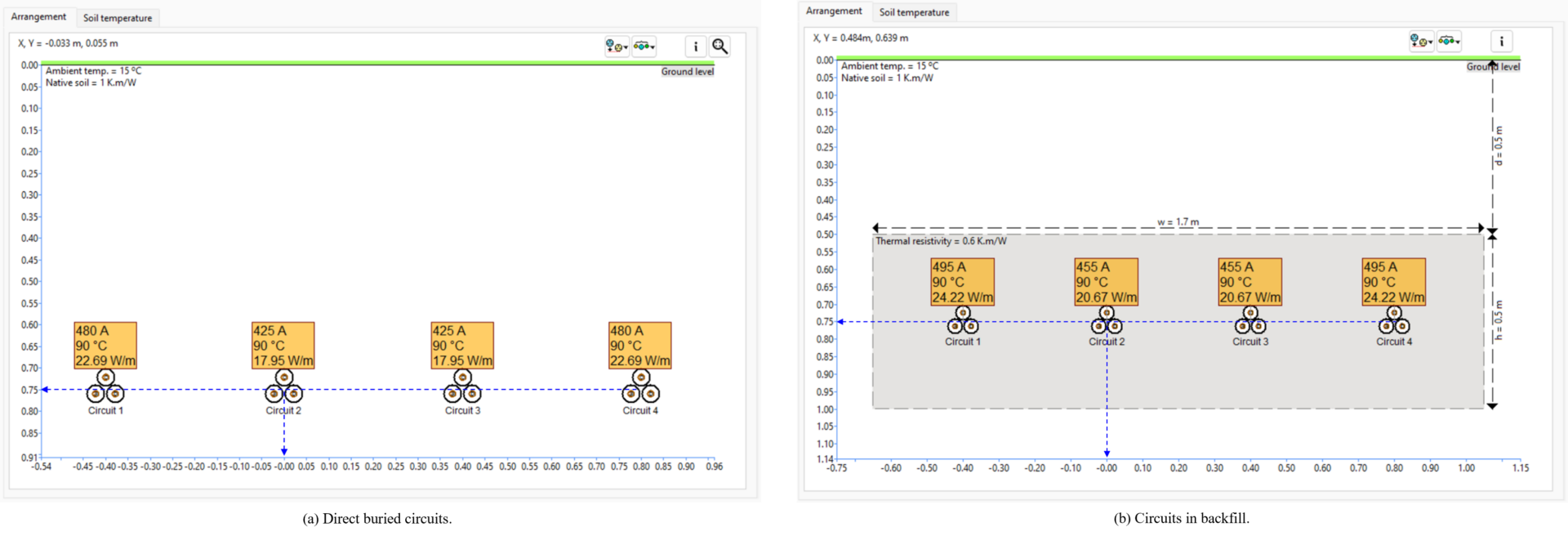
There are two cases shown in the Figure 1 below involving four medium-voltage cable circuits installed either in backfill or direct in soil. The native soil thermal resistivity was taken to be 1 K.m/W, the backfill thermal resistivity 0.6 K.m/W, and dry native soil thermal resistivity assumed to be 2.5 K.m/W at a critical soil temperature of 50 °C (based on a two-zone model).
The load factor was varied between unity (continuous maximum rated current) down to 0.75.
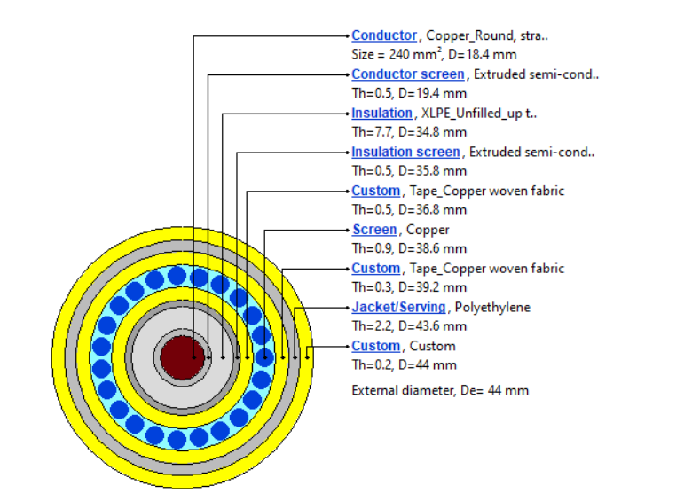
The cables are 33 kV single-core, featuring a copper 240 mm² conductor, XLPE insulation, copper wire screen, and an HDPE sheath. The wire screens are single-point bonded. More details on the cable model and installation arrangements can be found in the Appendix.
Results and Analysis
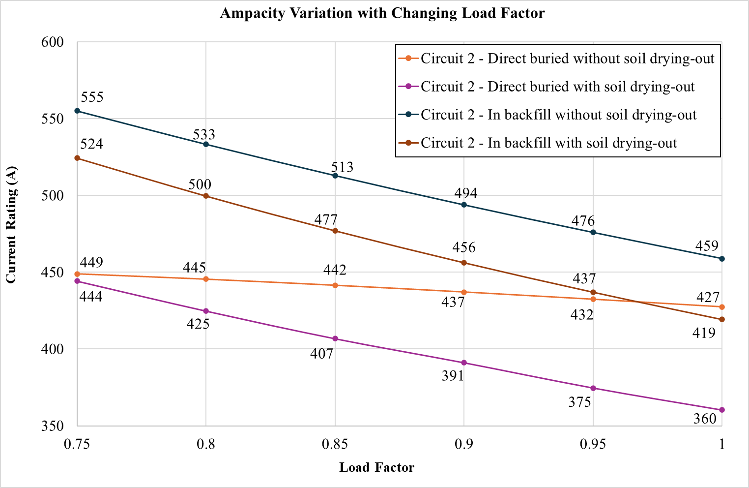
Figure 2 below shows the ampacity of Circuit 2 for both direct buried or in backfill, with or without considering soil drying, and for varying load factor.
The obvious and expected observations are:
The ampacity of cables in backfill is greater than that of direct buried cables.
As load factor reduces, cable ampacity increases significantly.
The new key observations and findings include:
The cable ampacity reduces significantly if soil drying-out is taken into consideration. This shows that it is a very important factor.
The cable ampacity increases linearly with non-unity (decreasing) load factor.
For direct buried cables with soil drying out the rate of this increase is less compared to without soil drying. Therefore, soil drying has more influence on the ampacity for direct buried than load factor.
For buried in backfill, the rate of the increase in ampacity with load factor being reduced was consistent when soil drying out was considered and when it was not. This demonstrates that the presence of the backfill “protects” the ampacity of the cables during soil drying out.
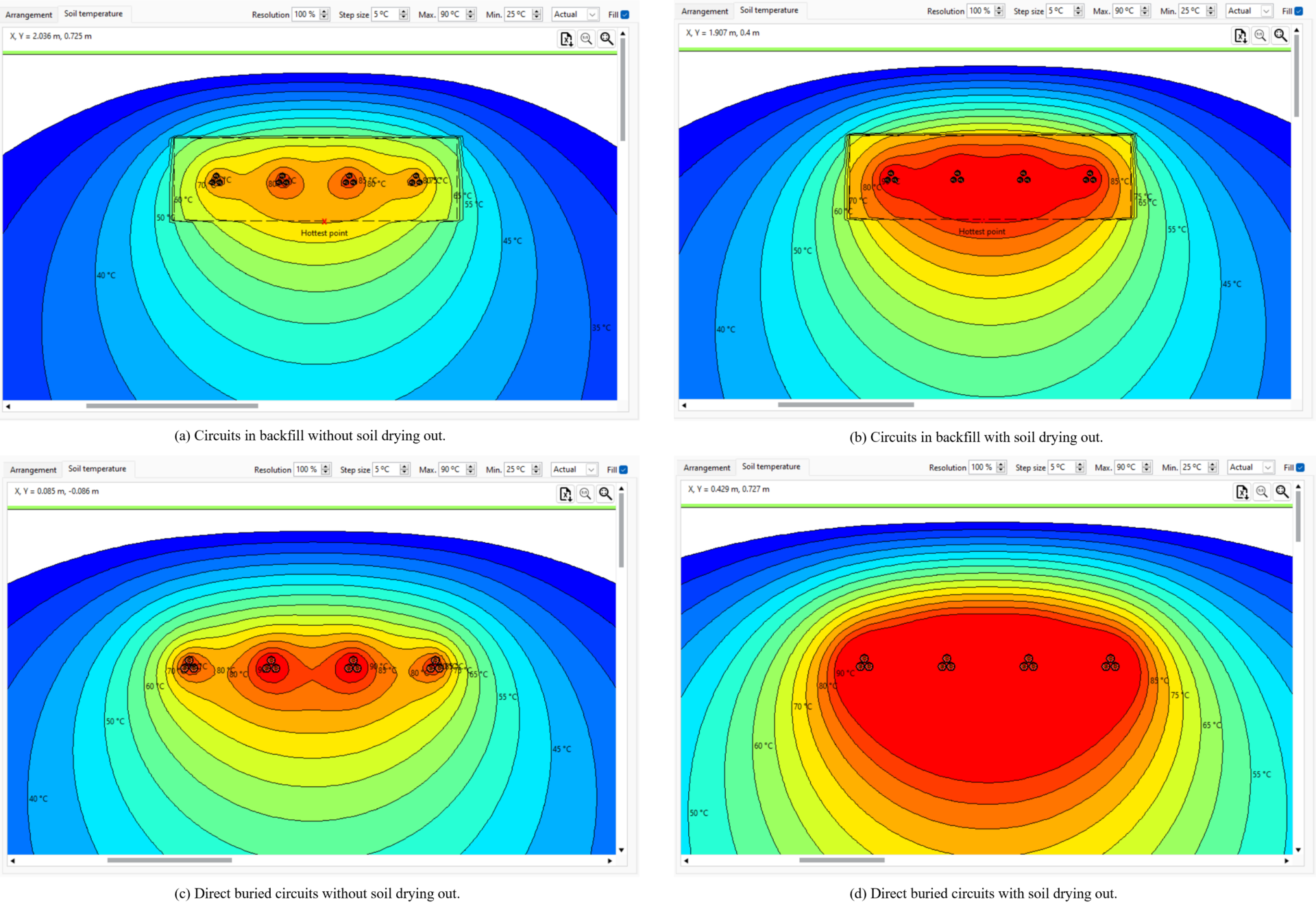
Soil drying out is clearly a very important factor when calculating ampacity for direct buried circuits and for buried in backfill circuits. Load factor is also important since it has a significant impact on ampacity. Circuits are also often buried together in groups so their mutual heating effects, as can be seen from the soil temperature plots in the figure below, are significant. Therefore, it’s imperative to have this solution like we have here, since it combines all the effects of these factors on the cable ampacity simultaneously.
To further demonstrate the differences among the four installation scenarios, Figure 4 shows the soil temperature plots for the circuits with an unity load. While the current rating remains at 485.54 A, the isothermal distributions can vary significantly for these scenarios. The new key observations and findings include:
If soil drying-out is taken into consideration, the soil around the cables becomes hotter.
If the circuits are in backfill, the soil around the cables is relatively cooler.
Considering soil drying-out helps designer to better evaluate the worst thermal conditions of buried cables.
Adding backfill can significantly improve the heat dissipation environments of buried cables.
Conclusion
This article has demonstrated how the ampacity of underground cables is affected by soil drying-out and cyclic load. Both direct buried cables and cables installed in backfill were investigated using ELEK Cable High Voltage™ Software in the case study. It compared the performance of cables installed under various conditions, including soil drying-out and non-unity load scenarios. The calculation results can assist professional engineers in better designing cable systems under complex thermal conditions.
Appendix
| Parameter | Value | Unit |
|---|---|---|
| Bonding Arrangement | Single Point Bonded | - |
| Arrangement | Trefoil | - |
| Phase Spacing | Touching | - |
| Circuit Spacing | 0.4 | m |
| Burial Depth of the Circuit’s Centre | 0.75 | m |
| Thermal Resistivity of Native Soil | 1 | K.m/W |
| Ambient Soil Temperature | 15 | °C |
| Thermal Resistivity of Backfill | 0.6 | K·m/W |
| Backfill - Width, Height and Centre | 1.7; 0.5; 0.75 | m |
| Critical Temperature of Soil Drying-out | 50 | °C |
| Thermal Resistivity of Dried-out Soil | 2.5 | K·m/W |
References
[1] IEC 60287-1-1, “Electric cables – Calculation of the current rating – Part 1-1: Current rating equations (100 % load factor) and calculation of losses – General”, 2014.
[2] IEC 60287-2-1, “Electric cables – Calculation of the current rating –Part 2-1: Thermal resistance – Calculation of thermal resistance”, 2015.
[3] CIGRE TB 880, “Power cable rating examples for calculation tool verification,” 2022.