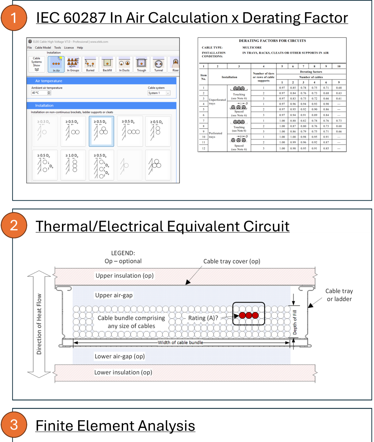
[1] IEC 60287 Series, “Electric cables – Calculation of the current rating,” International Electrotechnical Commission, Geneva, Switzerland, various publication dates.
[2] IEC 60364-5-52:2009, “Low-voltage electrical installations – Part 5-52: Selection and erection of electrical equipment – Wiring systems,” International Electrotechnical Commission, Geneva, Switzerland, 2009.
[3] ICEA/NEMA P-54-440-2009 (R2019), “Ampacities of Cables Installed in Cable Trays,” Insulated Cable Engineers Association and National Electrical Manufacturers Association, Rosslyn, VA, 2019.
[4] Demoulias, C., Labridis, D. P., Dokopoulos, P., & Gouramanis, K. (2007). Influence of metallic trays on the ac resistance and ampacity of low-voltage cables under non-sinusoidal currents. Electric Power Systems Research, 77(8), 899-909.
[5] S. Saadat, A. Borbuev, and F. de León, “Thermal Analysis of Power Cables Installed in Solid Bottom Trays Using an Equivalent Circuit,” IEEE Transactions on Power Delivery, vol. 32, no. 3, pp. 1565-1575, June 2017.
[6] IEEE Standard Power Cable Ampacity Tables, IEEE Std 835-2019, 2019.
[7] The Engineering ToolBox. Emissivity coefficients of some common materials. [Online].
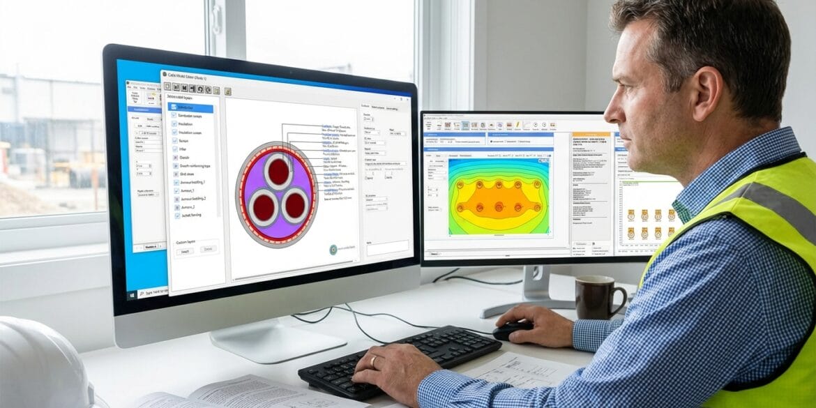
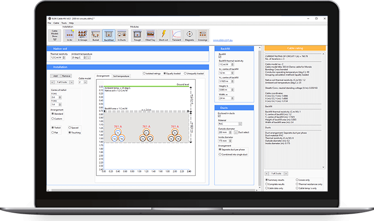
[8] ELEK Cable High Voltage Software.
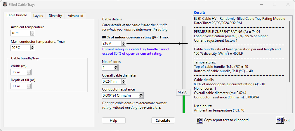 Filled Cable Trays module