Protecting substations from direct lightning strikes
Direct lightning strikes to substations causes physical damage and poses hazards for people. Because substations should operate reliably and because they are susceptible to lightning strikes, it is common practice to provide a Lightning Protection System (LPS) for both outdoor and indoor substations.
The specific requirements of an LPS for substations, the economic considerations and selection of adequate protection measures should be determined by way of a risk assessment.
An LPSis designed for a defined set of lightning current parameters based on the results of the International Council on Large Electrical Systems (CIGRE) research data. An LPS consists of both external and internal systems. The function of the external LPS is to intercept the lightning strikes with an air terminal system, conduct the lightning currents safely (via downconductors) to earth and disperse the current into the earth. The function of the internal LPS is to prevent dangerous internal sparking using either equipotential bonding or separation distance.
Four classes of LPS are used along with a corresponding set of construction rules which are based on the corresponding Lightning Protection Level (LPL).
The designer of the substation LPS will utilise the rolling sphere method to optimise the locations and configurations of lightning masts and shield wires in order to prevent direct lightning strikes to energised conductors, busbars, electrical equipment, support structures and buildings.
Protection of substation structures
In the protection of substation structures from direct lightning strikes, an LPS will be comprised of air terminals, overhead earth wires, downconductors, equipotential bonding and earthing terminations.
The vulnerability of structures is caused mainly by the electric field intensification associated with exposed points and corners on the upper surfaces of structures, conductors or busbars so air terminals and earth wires are installed to provide interception points for the lightning strikes.
Where to place lightning masts
Lightning masts are structures used for intercepting and conducting lightning strikes and consists of an air terminal which is mounted on a pole or on a structure. Based on [1], the following considerations need to be addressed for lightning masts:
- Lightning masts should firstly be placed to protect the most vulnerable parts of a structure (points and corners) and then the rolling sphere method should be used and more masts added or existing mast heights increased to ensure the rest of the structures least vulnerable parts are also covered by the protective shield produced by the mast.
- The air terminal part of lightning masts should be not shorter than 0.5 meters and no longer than 6 meters in height [1].
- If air terminals are used for protecting a sloped surface then they should be placed at the corners and there should be a minimum of 2 air terminals installed which are evenly spaced [1].
How to connect air terminals to ground (downconductors)
Downconductors are a direct connection to earth and should be provided for an air terminal.
Where multiple air terminals are used for protecting a single structure they should be interconnected with main conductors and downconductors should travel to earth at spacings not more than 20 m.
Earthing grids design for lightning protection
A buried earth grid or network should connect directly onto each downconductor of the lightning protection system and should achieve a low overall earth resistance (10 Ω or less at 50 or 60 Hz).
All metallic structures at ground level should have equipotential bonding installed.
What is the Rolling Sphere Method
The Rolling Sphere Method (RSM) is a technique for determining the zones of protection whereby a sphere is theoretically brought up to and rolled over the total structure.
The geometrical boundary of areas which are protected against direct lightning flashes can be determined using the RSM. All points of the structure that the sphere touches are exposed to direct lightning strikes and would need to be protected by air terminals.
Figure 1. – Zone of protection on a structure established by a rolling sphere

Another approach is to use the RSM to position and define the heights of lightning masts supporting air terminals connected to earth or earth wires and to use these structures such that they shield nearby structures or equipment in need of protection from direct lightning strikes.
Figure 2. – Structure protected with lightning masts

Figure 3. – Top down view of two lightning masts separated by distance L and area of protection

The RSM is conservative for flat surfaces because it assumes that these are as susceptible to lightning strikes as are exposed corners or edges of structures.
What is Protection Level
There are four LPL’s (I to IV) advised in the Standards and each protection level corresponds with a set of fixed parameters (refer to the table below). The interception efficiency of an LPS depends on the minimum lightning current parameters and on the related rolling sphere radius.
Table 1 – Rolling sphere radius and Protection level
| Protection level [1], [2] | Interception efficiency (%) [1], [2], [3] | Sphere radius, r (m) [1], [2] | Sphere radius - flat surfaces, ri (m) [1] | Interception current, Imin (kA) [1] |
|---|---|---|---|---|
| I | 99 | 20 | 60 | 2.9 |
| II | 97 | 30 | 60 | 5.4 |
| III | 91 | 45 | 90 | 10.1 |
| IV | 84 | 60 | 120 | 15.7 |
The selected LPL is achieved by installing a lightning protection system consisting of air terminals which establishes zones of protection enclosing the whole structure. For the calculation of these zones of protection, the rolling sphere method, with a modification for flat surfaces, is used.
The maximum values of lightning current parameters for the different lightning protection levels (not given here) are used to design lightning protection components.
The lightning sphere radius is assumed to have a fixed relationship with the peak minimum value of the interception (or discharge) current as follows [2]:
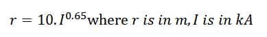
It is common to consider that PL III using a sphere radius of 45 m provides “standard” protection. PL I and II with sphere radius of 20 m and 30 m provide higher degrees of protection and therefore these protection levels will require a considerably greater number of air terminals.
Protection level III ensures that for striking distances of 45 m or more, the shortest distance to the structure is an air terminal. Such striking distances correspond with peak currents of 10.1 kA or greater, which has an interception efficiency of 91 %, meaning about 9 % of all possible strikes will have a lower current which would potentially not be intercepted.
Substation Lightning Protection Design Process
The lightning design process for protecting substations from damage and disruption caused by direct lightning strikes is as follows:
- Identify the parts of the installation which are vulnerable to direct strikes. Air terminals along with downconductors immediately below the air terminals should be allowed for.
- Select the desired interception efficiency from Table 1 and associated sphere radius.
- Establish zones of protection against direct lightning strikes which will enclose the entire area or structure(s) using the rolling sphere method. Also establish the maximum height of equipment to be protected inside these zones.
- Specify the heights and positions of the air terminals mounted onto existing structures where possible or on dedicated lightning masts and overhead earth wires as required for establishing the zones of protection according to the rolling sphere method. This is an iterative calculation process whereby the final solution is both economical and practical to construct.
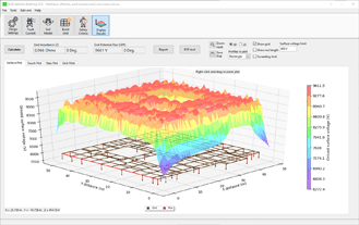
Figure 4 shows a 220 kV switchyard LPS design using a combination of air terminals mounted on standalone lightning masts (21.5 m overall height), air terminals mounted onto the building roof (17.5 m overall height) and gantry structures with earthwire connections (20 m overall height). The Protection level was custom between level I and II with a sphere radius of 29.5 m. The maximum height of equipment being protected within the zones of protection (the main busbars, switchgear and wall mounted post insulators) was 11 m. The figure is an output plot from automated software calculations which shows that the equipment inside the zone of protection is shielded from direct lightning strikes.
Figure 4. – Switchyard LPS – Zone of protection diagram from SafeGrid Earthing Software

References
[1] AS/NZS 1768:2007 Lightning Protection
[2] IEC 62305-1:2010 Protection Against Lightning
[3] Anderson and A.J. Eriksson, Lightning Parameters for Engineering Application, CIGRE Electra No. 69 (1980), p. 65-102