Introduction
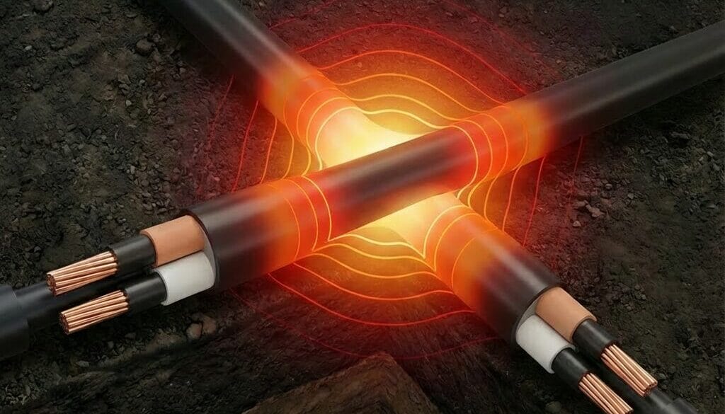
The thermal resistance of the external environment which surrounds power cables has the largest impact on the temperature rise of the conductor and hence the current rating compared with other factors. That is why plenty of effort is taken by asset owners and cable systems designers to reduce the external thermal resistance for cables to maximise their current-carrying capacity.
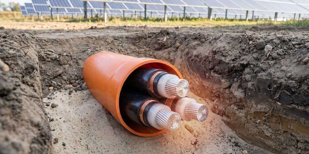
It is common practice to install buried groups of low- or medium voltage cables inside duct banks which allows circuits to be well-organised and protected in the same trench (or multiple trenches). Concrete is often used to surround the cables in a duct bank and has relatively low thermal resistivity but also is not subject to moisture migration (drying-out effect), which guarantees higher cable current ratings.
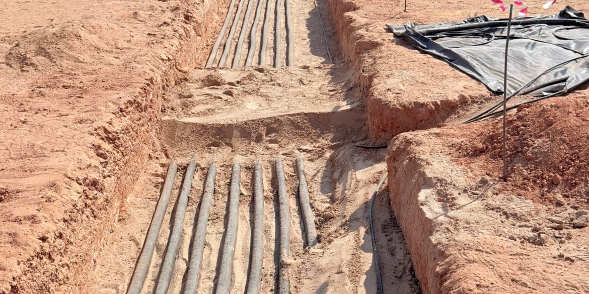
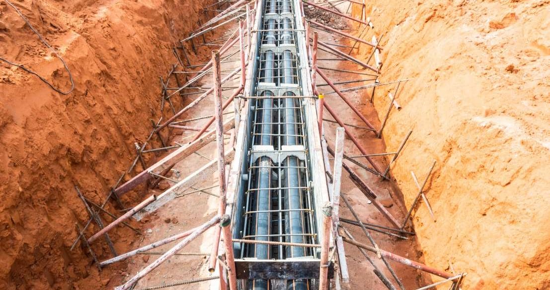
High-voltage cables are commonly buried in trenches and surrounded with an approved bedding material (typically thermally stabilised sand) which has suitable low thermal resistivity. Backfilling is most effective when the thermal resistivity of the native soil is high but also can be an effective method of avoiding moisture migration (leading to high thermal resistivities) in the vicinity of the cables. Multiple transmission cable circuits may be installed in separate backfills within the same transmission easement. Joint bays made of precast concrete sections or manufactured on-site and can be unfilled or filled with stabilised sand.
Once cables are installed in a duct bank or a backfilled trench the remaining space left is filled either with the native soil (often sieved for rocks) or a different material brought in from off-site.
The most widely used documents for cable current rating calculations are the IEC 60287 [ref. 1] series of standards (which adopts an equivalent thermal model solved using analytical methods). Whereas most real-world cases including those described above involve multiple zones with different thermal resistivity, the IEC standard provides a calculation method to allow for the presence of a single a duct bank or backfill only and the dimensions are also limited.
For accurate current rating calculations of cables installed in multi-layered or multi-zoned soils with varying thermal resistivity the Finite Element Method (FEM) is proven to be highly effective.
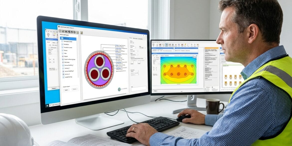
The IEC 60287 and FEM calculations herein were performed using ELEK Cable HV Software™.
Limitations of IEC 60287 to a single backfill
IEC standard 60287 provides an equation for the external thermal resistance T4 of a single buried cable. For groups of equally loaded or unequally loaded buried circuits the mutual heating within the soil is accounted for assuming the superposition theory.
When it comes to accounting for the presence of a backfill surrounding the buried cables the IEC standard provides a T4 correction factor based on an equivalent backfill radius, \(r_b\) as follows:
\(r_b = e^{\frac{x\big(-\frac{x}{y}+\frac{4}{\pi}\big)\ln\big(1+\frac{y^2}{x^2}\big)}{2y}+\ln\big(\frac{x}{2}\big)}\)
Where x is the shorter side of the backfill and y is the longer side, both in millimetres.
For example, in Figure 1 below the equivalent radius based on backfill dimensions of 1000 mm wide and 400 mm high is 398 mm.

Limitations of the IEC 60287 standard method includes:
- Only a single backfill can be modelled.
- The dimensions of the backfill are limited to y/x less than 3 where y is the longer side and x is the shorter side of the backfill.
- Backfill thermal resistivity must be lower than the surrounding soil (which makes sense – but is still limiting when multiple zones of different soil resistivity are needed to be modelled).
The finite element method of calculation does not have these limitations.
Finite element calculation method explained
A computer algorithm was developed which is designed to determine the steady-state current rating of buried cables installed inside multiple (adjacent and touching or adjacent and spaced) duct banks or backfills with different thermal resistivity.
The algorithm combines parts of the IEC 60287 standard calculation method but computes the values of T4 (external thermal resistance of the cables) using the finite element method and the current rating (or operating temperature) is obtained using the standard method.
The finite element method is used to extend the capabilities of the IEC standard method where the following capabilities are highlighted:
- Model an unlimited number of rectangular areas (zones) of difference thermal resistivity.
- Model an unlimited number of circuits of different cable types.
- Non-isothermal ground surface calculations which consider convection by air with velocity.
- Calculate the current rating of cables installed in filled troughs.
- Compute steady-state current rating or operating temperature.
- Transient analysis, cyclic loading and emergency ratings are supported.
Therefore, the finite element method is more flexible than the IEC method. FEM is also more accurate since it avoids several of the standards assumptions. For example, whereas the IEC standard assumes no heat flows between the soil and the ground surface to the air (isothermal ground surface), the use of FEM avoids this approximation.
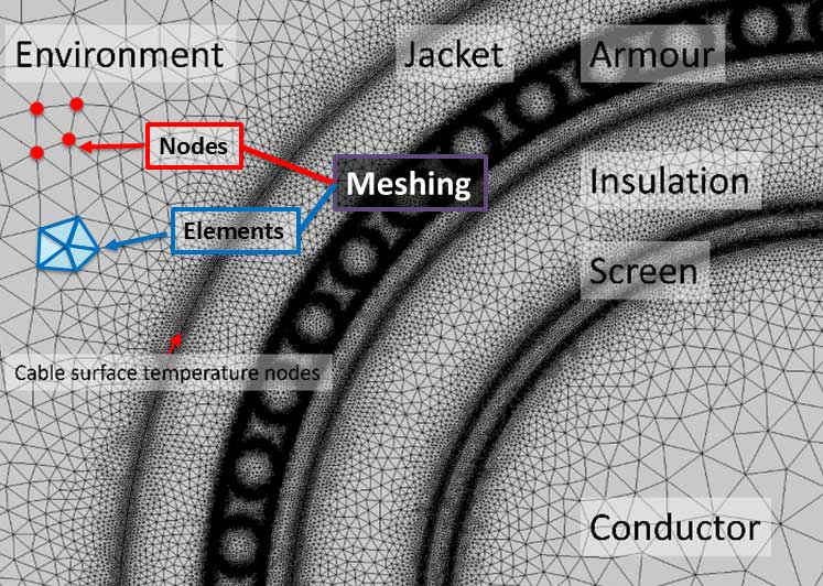
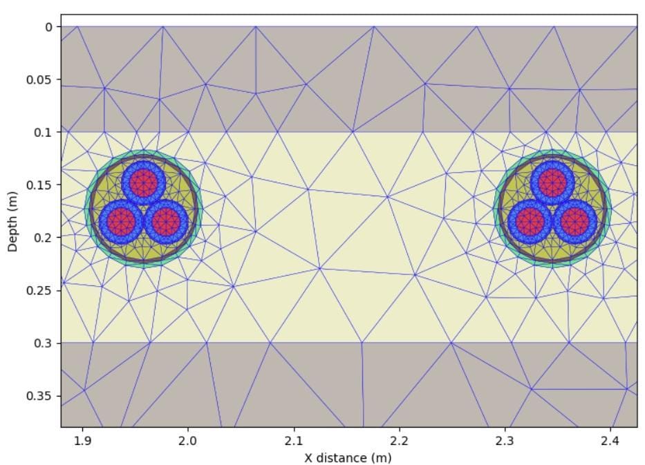
In FEM the space is subdivided into smaller parts known as finite elements (refer to Figures 2 and 3 below as examples). These elements take the shape of a tetrahedron or a triangle. The domain of interest is space discretised, and this is implemented by constructing a mesh of the object.
The formulation of finite element method results in a system of algebraic equations. These equations that model the finite elements are then assembled into a larger system of equations that models the entire problem. The solution to the problem is reached by minimizing the mean squared error error function. For the analysis of cables, it is assumed to be a 2D space.
Example calculation - Multi-circuit with multiple backfills
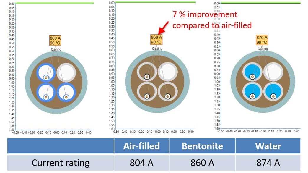
There are two high-voltage cables circuits to be installed in separate thermally stabilised sand backfills. The cables are 132 kV single core, copper 1200 mm2 conductor, XLPE insulated with copper wire screen and PVC sheathed. The wire screens are single point bonded.
There are also two medium-voltage circuits installed a nearby surface trough. The cables are 22 kV multicore, aluminium 500 mm2 conductor, XLPE insulated with steel wire armouring and PVC sheathed.
The different thermal resistivities of the multiple zones of the environment are:
- Native soil 2 K.m/W.
- Stabilised sand for high-voltage cable backfills and used inside the trough 1 K.m/W.
- Concrete walls of the filled trough 1.2 K.m/W.
- Soil (sieved) returned to the trench of the high-voltage cables 1.5 K.m/W.
For FEM-based non-isothermal ground surface calculations, the ambient air temperature was 25 degrees Celsius and the soil surface convection was based on still air (0 m/s).
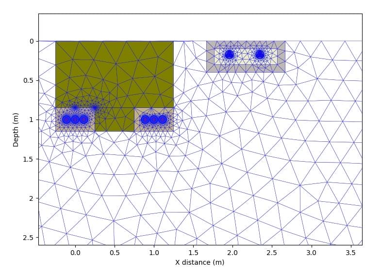
Meshing of the cables and environment
The first step to the FEM calculation was to apply a meshing algorithm to the complete environment including the soil zones with different thermal resistivity.
Results – calculated current ratings
The cables and buried environment with multiple zones of different resistivity were modelled inside the FEM module of ELEK Cable HV Software™ Version 5.1.
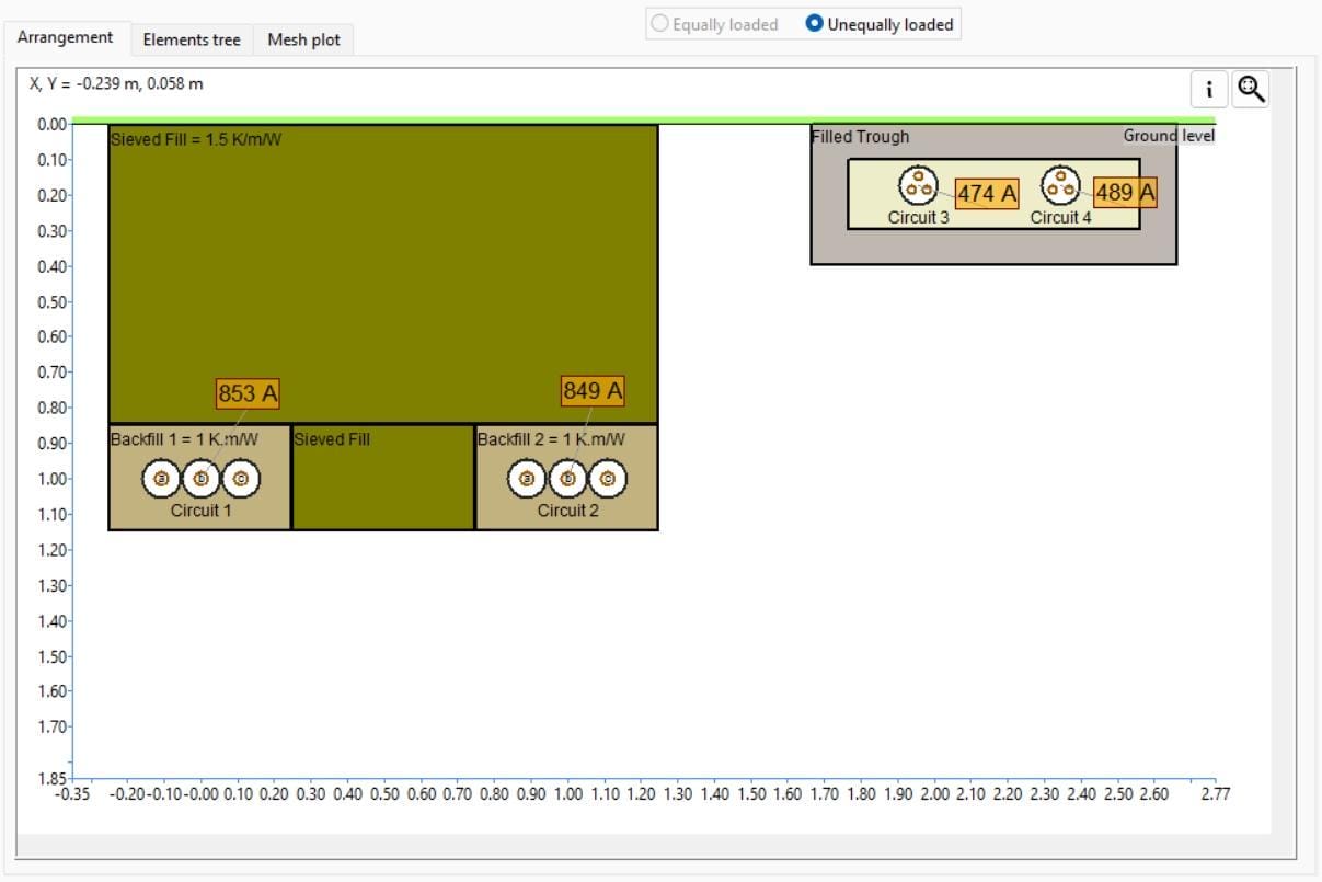
The calculated current ratings for the 132 kV and 22 kV cable circuits are shown in Figure 4.
A sensitivity analysis was performed by calculating the current ratings where certain aspects of model are removed to examine their importance based on change to the current ratings.
The table below shows for the “Base Case” (where all aspects are included in the model as shown in the image above) the minimum current rating for the 132 kV and 22 kV circuits is 849 A and 474 A respectively.
Case 2 – If the sieved fill which has a lower thermal resistivity compared to the native soil is neglected in the model, then current ratings will be underestimated by as much as -10.13 % for the 132 kV circuits.
Case 3 – Ignoring the presence of the filled trough and the 22 kV circuits has a small effect on the rating for the 132 kV circuits resulting in a relatively minor over-estimation by 1.06 %.
Case 4 – Neglecting to include the sieved fill and filled trough results in a significant underestimation of the 132 kV circuit current rating, which makes sense considering this is Case 2 and Case 3 combined.
Case 5 – This shows there is a small difference with Case 4 when you assume the backfills are combined and not separated, if you were limited to assuming a single backfill as is the limitation for the IEC Standard method. Note however the (T4) results for a simple case such a single backfill between the IEC method and the finite element method will (usually) be quite different especially when the cables are buried at 1 m or shallower and/or in low thermal resistivity soils – this is mainly due to the extra-ability of FEM to model the convection of heat to the air at the ground surface.
| Case description | 132 kV circuit | 22 kV circuit | Difference in current | |
|---|---|---|---|---|
| 1 | Base Case - All Circuits and Zones of Resistivity | 849 A | 474 A | - |
| 2 | No Sieved Fill | 763 A | 461 A |
-10.13 % (-86 A) - 132 kV -2.74 % (-13 A) - 22 kV |
| 3 | No 22 kV Circuits and No Filled Trough | 858 A | - | 1.06 % (+9 A) |
| 4 | Separate Backfills Only | 772 A | - | -9.07 % (-77 A) |
| 5 | Single 1.5 m Wide Backfill Only (similar to IEC Limitation) | 774 A | - | -8.83 % (-75 A) |
Standard values of native soil thermal resistivity
Soil thermal resistivity has significant impact on the current rating for buried power cable systems.
Soil is a composite of different minerals, organics, water, and air. The thermal resistivity of soil depends on the composition of the materials (the shape, size, and compaction of the particles) and physical properties moisture content and density. Moisture content and dry density have the biggest impact on the thermal resistivity of soils and as one or both factors increases the thermal resistivity decreases.
In the absence of actual measured values various countries adopt standard (assumed) native soil thermal resistivity values for cable rating calculations. Standard values vary between 0.5 to 3 K.m/W however the most common nominal value for native soil is 1.2 K.m/W.
Refer to IEC Standard 60287-3-1 for nominal values of thermal resistivity on a per country basis.
Conclusions
Recent advances in computing power and as the time required to build and solve models has reduced substantially, this has made the finite element methods suitable for everyday use including for electrical power cable current rating calculations.
The finite element method of calculating cable current ratings is more accurate than the analytical methods from IEC Standard 60287 which have significant limitations.
One limitation of the IEC Standard which FEM overcomes is the ability to model multiple zones with different thermal resistivity. FEM also resolves the limiting assumption of an isothermal ground surface layer by adding the ability of the user to consider the effects of ground surface heat transfer.
The buried multi-circuit example calculation given here showed the importance of being able to consider all the areas of the ground nearby with different thermal resistivity to the native soil especially if their relative area is substantial such as a sieved fill which is used to fill the trench after the cables are installed.
Furthermore, since FEM provides the ability to model all the cable circuits and the thermal environment as closely as possible to resemble reality this gives piece of mind that the calculated results will be matching with the actual installed current ratings.