Table of Contents
What is voltage drop?
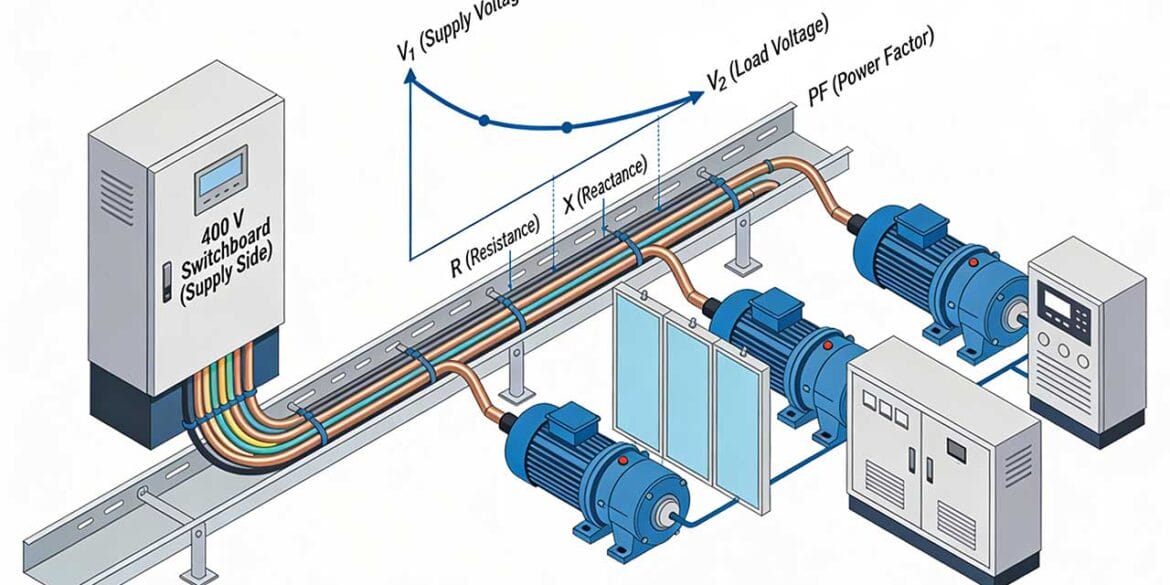
The voltage drop in a circuit represents the difference between the voltage from the supply end and the voltage at the load end. Voltage drop depends on the current load, cable type, and other factors, and has a significant impact on the minimum cable size.
The standards set allowable percentage voltage drop limits.
Voltage drop equation
When determining the maximum voltage drop, an equation can be applied under the assumption that the power factor of the cable is equal to that of the load.
This equation can be expressed as:
\(V_d = I \cdot Z_c\) (Eq. 1)
Where:
- Vd is voltage drop in cable, in volts
- I is current flowing through cable in amperes
- Zc is impedance of conductors in ohms whereby,= √((Rc2+ Xc2))
Rc represents cable resistance which is a function of conductor material, size and operating temperature. Xc represents cable reactance being a function of shape and phase spacing.
Note for DC voltage drop calculations the value for reactance Xc is zero.
Use the Free Voltage Drop Calculator for easy and accurate voltage drop calculations.
Voltage drop based on power factor
In a case where the supply and load voltages differ in terms of phase angle, another set of equations are to be used to compensate for this change. When the current is leading the voltage, the supply voltage ends up being smaller than the load voltage. The voltage drop IZc is identical in all power factor cases but is different in terms of phase angle except for when the cable and load power factors are equal which shows the voltage drop Vd is a maximum of IZc. The following equations apply for lagging power factors.
For a single-phase system
\(V_{d1\phi} = IL[2(R_c cos \theta + X_c sin \theta)]\) (Eq. 2)
For a balanced three-phase system
\(V_{d3\phi} = IL[\sqrt{3}(R_c cos \theta + X_c sin \theta)]\) (Eq. 3)
Resistance and cable operating temperature
The resistance of a cable is dependent on temperature and the standard provides tables of resistance for a particular operating temperature.
In a situation where the cable operating temperature is less than the maximum figure provided by the Standard tables, the conductor temperature can be estimated using the following equation:
Where:
- I0 = operating current, in amperes
- IR = rated current provided in the current rating tables (from Tables 3.9-3.32 in AS/NZS 3008.1.1-2025)
- 00= operating temperature of cable when carrying , in degrees Celsius
- 0A= ambient air or soil temperature, in degrees Celsius.
Once cable operating temperature is calculated then the cable resistance can be selected. In the case of AS/NZS 3008.1.1-2025 the Tables 4.5, 4.7, 4.9, 4.10, 4.12 and 4.13 and d.c. Tables 4.6, 4.8, 4.11 provide resistance values for the following operating temperatures: 25oC, 30oC, 45oC, 60oC, 75oC, 80oC, 90oC, and 110oC, and the calculated operating temperature is then rounded-up (more conservative) to the nearest temperature.
Voltage drop for unbalanced multiphase circuits
In an unbalanced system, current will be flowing through the neutral conductor as illustrated by the phasor diagram in Figure 1:

There are two ways of dealing with voltage drop in these cases. A conservative solution is to assume a balanced three-phase load and to perform calculations using the current flowing in the heaviest loaded phase. However, where the currents in each phase can be shown to be of different magnitudes for consistent periods then voltage drop can be calculated on a single-phase basis by summing the voltage drop in the heaviest loaded phase plus the voltage drop in the neutral as shown by the equation below.
In the next section, we will provide an example voltage drop calculation.
Example voltage drop calculation
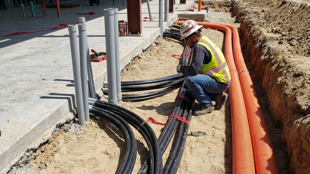
Single core cables with copper conductors and XLPE insulated are connected to a 3 phase 400 V supply. The installation is buried direct in the ground (reference ambient temperature is 25oC) over 120 m length of run. The load current is 240 A at power factor of 0.9.
What is the 3-phase voltage drop?
Step 1: Determine cable operating temperature
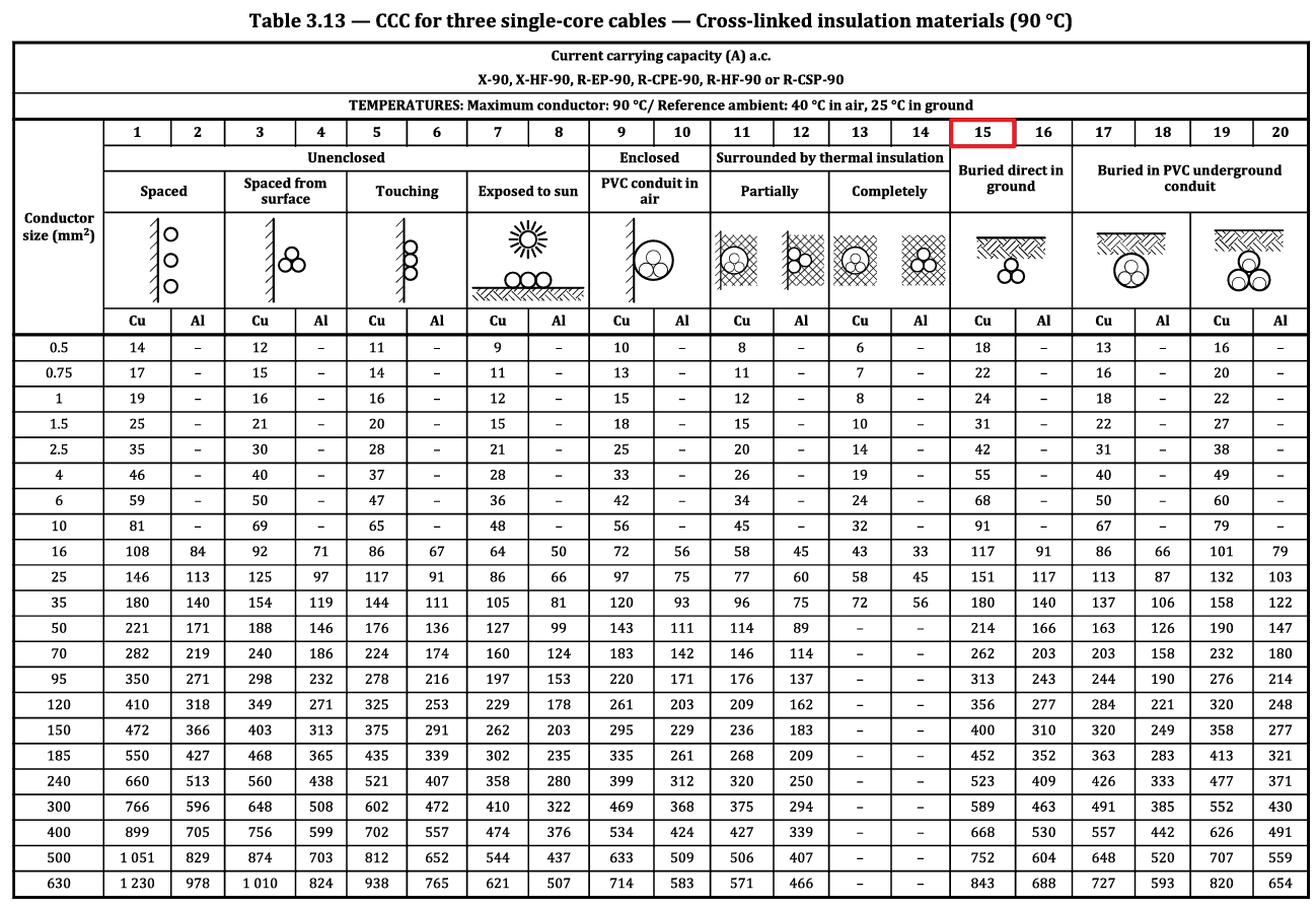
The minimum conductor size from current-rating Table 3.13, column 15, is 70 mm2, which has a maximum current rating of 262 A.
Figure 2: Illustration of the cable buried directly in the ground.
The normal use operating temperature for XLPE insulated cables is 90˚C. Using Equation 4 for cable operating temperature:
\(\theta_0 = (90^{\circ} – 25^{\circ})(\frac{240}{262})^2 + 25^{\circ}\)
Step 2: Determine cable resistance based on cable operating temperature
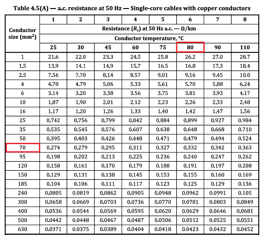
Using Table 4.5(A) (refer to Appendix 2 below) we can find the AC resistance of the cable that matches the conductor size and is at a conductor temperature closest to the cable operating temperature calculated in Step 1. Since we calculated a temperature of 79.5°, we should round up to 80° as the most accurate temperature to use.
Per Table 4.5(A), the resistance of a cable with a 70 mm2 copper conductor and an operating temperature of 80° is 0.332 Ω/km, or 0.000332 Ω/m.
Step 3: Determine cable reactance
The reactance for single core cables depends on the cable type and separation of the cables.
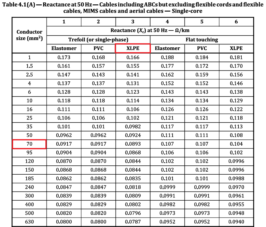
Using Table 4.1(A) (refer to Appendix 3 below) we can find the reactance at 50 Hz.
Our cables are in a trefoil arrangement, therefore from Column 3 the cable reactance is 0.0893 Ω/km, or 0.0000893 Ω/m.
Step 4: Calculate voltage drop based on power factor and cable operating temperature
We will use Equation 3 to calculate the 3-phase voltage drop. For this we need the phase angle of the load based the given load power factor as follows:
\(\theta = cos^{-1}(0.9)\)
\(\theta = 25.84193276^{\circ} = 0.4510268 \; rads\)
\(sin\theta = 0.43588989\)
Now, we have all parameters needed to calculate the three-phase voltage drop:
\(V_{d3\phi} = 240 \cdot 120[\sqrt{3}(0.000332 \cdot 0.9 + 0.0000893 \cdot 0.43588989)]\)
\(V_{d3\phi} = 16.81 \; V\)
The voltage drop as a percentage of the supply voltage is 16.81 / 400 V, or 4.2%.
Appendices
Appendix 1 – Table 34 with relevant column highlighted in red
Appendix 2 – Table 4.5(A) with relevant rows and columns highlighted in red
Appendix 3 – Table 4.1(A) with relevant rows and columns highlighted in red
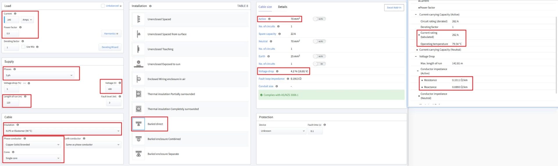
Appendix 4 – Example in Cable Pro Web