Table of Contents
Abstract
This article analyses the magnetic fields produced by electrical power cables installed in various configurations under varying conditions in the context of a health and safety-related issue. A calculation module in-built into ELEK Cable High Voltage Software has been used for calculating the results based on the Biot-Savart law. EMF mitigation techniques are also explained.
I. Introduction
There are electric power cables in use all around us. The current that a cable carries generates a magnetic field that emanates in all directions. Medical research has shown that exposure to magnetic fields above safe limits can have a significant detrimental effect on health. The International Commission for the Protection against Non-Ionizing Radiation Protection has set 1 mT as the reference limit for occupational exposure and 200 µT as the public exposure limits [1, 2].
For new or existing power projects involving electric cables, since these cables often carry high currents and are installed low to or under the ground near to where people cohabit there is often a requirement to calculate and to measure the magnetic field. ELEK™ Cable HV software has a specialised module for easily and accurately calculating the magnetic fields from cables.
This paper provides a parametric study of factors affecting the magnetic field around a cable such as soil permeability, load current magnitude and phase angle at varying measurement distances. The presented results include those for multiple circuits, installed in various industry-standard configurations such as horizontal, vertical and trefoil and for varying load currents which are balanced or unbalanced.
The assumptions of the calculations are that:
- The cables are infinitely long conductors.
- The air and/or soil is assumed to be electromagnetically homogeneous, isotropic and linear.
- Eddy currents losses can be neglected because of low penetration depth for earth electrical resistivities between 10 – 100 Ω-m (assumed) at 50 / 60 Hz.
- Induced currents in the cables, neutral wires, neighbouring cables and all other structures are ignored.
- For cables in air or soil relative permeability is 1.
- Currents used are RMS values.
- The superposition principle is applied where the field produced by each cable is combined to obtain the total field.
II. Mathematical Formulation
A. Magnetic field of a single conductor
The Biot-Savart law explains the fundamental quantitative relationship between an electric current which is flowing and the magnetic field it produces.
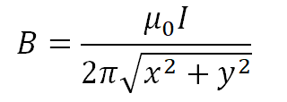
The value of the magnetic field (B) at a point in space with relative permeability μ0 is the sum of all the contributions from each small element or segment of a current-carrying conductor. For a very long straight conductor carrying current the magnetic field at a nearby point is proportional to the value of the current and inversely proportional to the perpendicular distance from the conductor to a given point (x, y) as follows


B. Magnetic field of multiple conductors - same phase angle
The magnetic field produced by multiple conductors is calculated as the summation of the magnetic fields caused by the individual conductors. Consider n conductors carrying currents I. The positions of the conductors are (xi,yi).
As derived from earlier equations the horizontal and vertical components of the magnetic field is the summation of the components of each individual conductor from a measurement point (xk,yk).
Horizontal component,

Vertical component,


So, the magnetic field at any point (xk,yk) is

C. Magnetic field of multiple conductors - different phase angles
The current in each conductor can be resolved into the corresponding in-phase and out-phase components. Therefore, if we consider a three-phase circuit, the horizontal and vertical component of the magnetic field will have components due to in-phase and out of phase currents for each conductor.
Consider a three-phase system carrying currents with a phase difference of 1200.


D. Effects of soil permeability on magnetic field
Electric power cables are commonly buried underground, and the magnetic field needs to be calculated above the ground surface level. In this case the magnetic field depends on the relative permeability of the two adjacent mediums being the air and the soil. To calculate the magnetic field in the air caused by a current flowing in a buried conductor(s) the image method is used which considers soil permeability.
An image current in the same direction appears if a current is placed parallel to a plane surface of differing permeability. The vector potential in the other region can be calculated by summing the contributions from the original current and the image current. This image current is perpendicular to the surface. So, the image current is

The new current is

III. Simulation Results
The simulations are carried out for single and multiple circuits of single core high voltage cables arranged in different buried configurations. The current ratings were calculated using the ELEK™ Cable High Voltage software.
A. Magnetic field as a function of soil permeability and current magnitude
The magnetic field produced by a current-carrying buried cable is directly proportional to the soil permeability. Various types of soil and their magnetic permeabilities are discussed in [3] and are shown to not vary by a lot.
A simulation was performed with 530 A current for a standard three phase circuit with the cables touching and buried 1 m below the ground. Measurements of magnetic field were taken at ground level. Figure 2 shows that the minimum magnetic field (6.9498 µT) was obtained at μrm=1 and as soil permeability increases so too does the magnetic field increase.

Figure 2. – Magnetic field densities for varying soil permeabilities for a single circuit horizontally laid UG cable.
Another simulation was carried out for multiple (2) circuits. Both three phase, single core cable circuits were laid horizontally. The circuit on the right-hand side carried a much lower current than that on the left. The separation between the circuits was 2 m.
Figure 3 confirms that the magnetic field is stronger for higher currents. This is shown by the maximum magnetic field at all soil permeabilities occurring at the centre of the cable carrying the largest current on the left.

Figure 3. – Magnetic field for varying soil permeabilities for a multiple circuit horizontally laid UG cable.
B. Magnetic field as a function of phase sequence
Phase sequence and the relative positions between laid cables relates to an interesting practical problem. The magnetic fields from adjacent cables interact with one another according to the equations presented earlier in this paper. The way or the degree in which they interact must be balanced to ensure the currents are balanced (equal) between phases. Unbalanced loading of cables within circuits is undesirable and could result in overheating. There are recommended phase arrangements / configurations given by industry standards which aim at avoiding or at least minimising phase current unbalance.
For example, one industry-standard recommends the following physical phase arrangement for two three-phase circuits.
Figure 4 shows the variation of magnetic field with the change in phase sequence for two three phase circuits arranged as above. The current carried by the conductors are 465A. The minimum magnetic field of obtained is 5.398µT when the phase of the first circuit is [0 -120 120] and that of the second circuit is [120 -120 0] i.e. ABC – CBA. This confirms what the industry-standard has recommended. It is simple to verify the various other recommended configurations by plotting the resultant magnetic field.
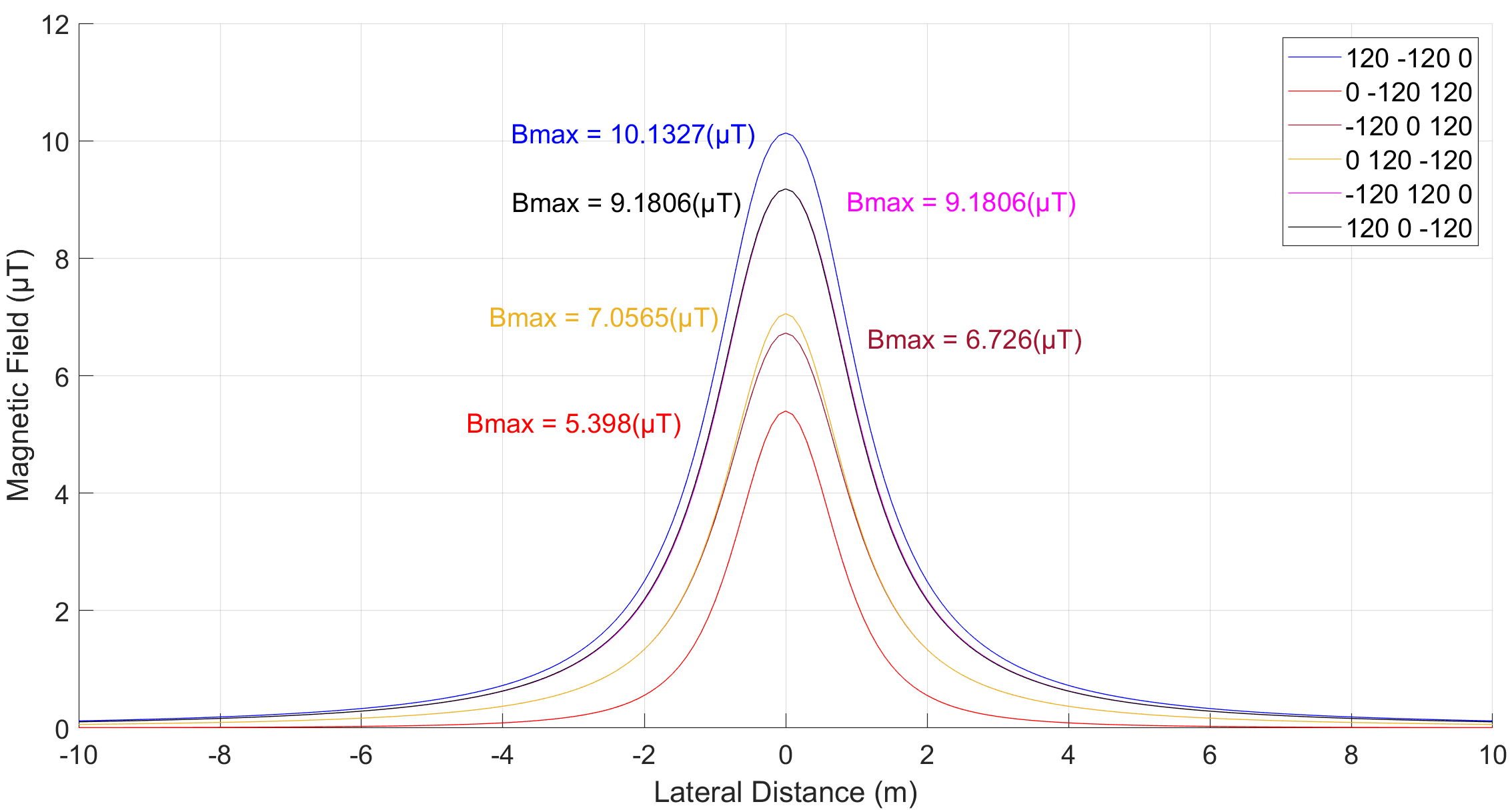
Figure 4. – Magnetic field for 2 conductor/phase horizontal configuration
C. Magnetic field and distance of measurement
Magnetic field is calculated and measured at a relevant height to establish what the values of exposure might affect people (typically 1 m above ground level).
Since the magnetic field is inversely proportional to the distance of measurement then as the distance from the cable increases the magnetic field decreases. Fig. 5 shows the variation of magnetic field with distance from a horizontally laid cable carrying 465 A. The minimum magnetic field obtained is 1.739 µT when the measurement is carried out 1 m above the ground.
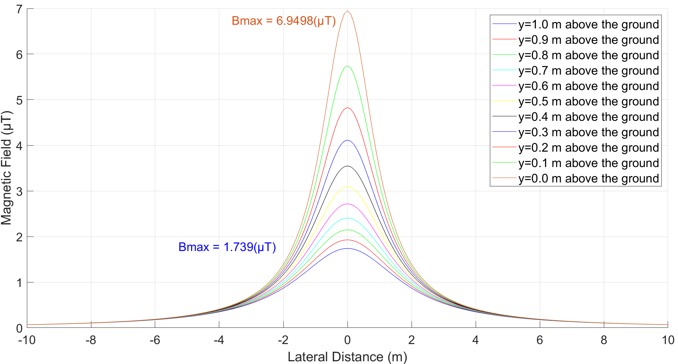
Figure 5. – Magnetic field for a horizontal cable configuration
IV. EMF mitigation techniques and systems for cables
When an electrical engineering designer plans a new cable circuit(s), the magnetic field generated is calculated and compared to safe limits. Where the specified limits are exceeded, then mitigation may be required.
Where mitigation of magnetic fields is required, it must be decided what sort. This includes either:
- Mitigation to reduce the magnetic field directly above the cables; or
- Mitigation to reduce the magnetic field to below a limit at a certain distance away; or
- Mitigation to minimise the width (corridor) within which the field limit is exceeded.
Mitigation techniques include devices but also cable management or phase rearrangement.
A. Cable arrangements
The arrangement of cables and the phase sequence both have a significant effect on magnetic fields. Cables arranged in trefoil will have lower magnetic field than in flat formation. However, it may not be possible to arrange the cables in trefoil (near junction boxes it’s often impossible) due to physical constraints or for thermal reasons. Refer to our technical publication on cable arrangements for reduced magnetic field.
The field decrease being inverse with distance rule is only applicable for single-core cables in flat or trefoil arrangements. For multicore cables the fields are greatly reduced especially since the cores are normally twisted to form a helix.
B. Inverted U-shaped metal plates
It has been shown by many studies that an inverted U-shaped metal screens placed on top of and around the cables provides the best reduction of magnetic fields. A shielding factor higher than 10 times can be obtained for U-shaped metal plates welded together longitudinally along the cable length. The plates can be non-magnetic metal like aluminium or copper, or magnetic steel.
A problem with U-shaped screens is they can be difficult to install especially around buried cables that require to be installed in thermal backfills requiring compaction.
C. Steel shielding enclosures
One mitigation technique involves installing the cables inside a closed metallic shield and arranging the cables in a trefoil configuration. To determine the current rating of the cable arrangement inside the shield the loss equations of IEC 60287-1-1 for pipe-type cables can be used provided the cables are installed in an enclosure made from normal commercial-grade steel. If the rating of the cables is reduced too much with the cables touching in trefoil then plastic ducts can be used to separate the cables to reduce the mutual heating between the phase cables.
D. Metal plates
There is a magnetic field reduction technique that involves installing highly conductive metal plates in close proximity to the cables. Essentially the magnetic field causes an induced current which causes eddy currents to flow in the metal plate which cancels the original fields.
The thickness of the plates should be at least 2 mm but thicker plates gives better results. It is recommended to make the metal plate thickness to be greater than the current skin thickness (12 mm for aluminium and 9 mm for copper at power frequency).
The width of the plate is also very important since the shielding effectiveness decreases strongly with distance from the centre of the plate/cables. This phenomenon results in two peaks in the magnetic field at the edges of the plate if the plate is not sufficiently wide. The U-shaped screening plate mentioned above requires less width than a flat metal plate.
The metal plate does not necessarily need to be continuous and there can be gaps but these gaps will cause a reduction in the shielding effectiveness. Metal plates may be overlapped and offset (similar to how bricks are laid as staggered in a wall) and the overall effect is similar to that of a continuous metal plate. Note the separate overlapping plates do not need electrical continuity.
V. Conclusion
Power cables emit magnetic fields which can present a health and safety problem. Even when the resultant magnetic field from a group of cables is not evenly distributed then this can cause unbalances of currents in the cables which is undesirable. It is pertinent to calculate the magnetic fields produced by cables or groups of cable circuits during the design phase to avoid any issues and allow the making of any necessary changes to their configurations.
To understand how to make the necessary changes one must understand how magnetic field varies with factors including current (generally non-changeable), spacing between cables, depth of burial, phase sequence, soil permeability (varies by little) and point of measurement. As soil permeability increases the magnetic field also increases irrespective of the configuration of the circuit but by very little for standard soils. The same is the case for multiple circuits. As the distance of measurement from the cable increases the magnetic field decreases. For buried cables the maximum magnetic field occurs at ground level and the field decays as the distance is increased. The effect of phase sequence on the magnetic field is also quite prominent. A configuration of cables of different phases which produces the highest overall magnetic field (compared with other relative configurations) will result in a worst-case phase current unbalance.
V. Appendix
Soil permittivity values from [3].
| Rock or soil type | Relative magnetic permeability (µ/µ0) | Source of Information | ||
|---|---|---|---|---|
| Typical Value | Range | |||
| Soil and sedimentary rock (general) | 1.0006 | 1.00001 to 1.001 | Nettleton (1940) | |
| Alluvium (NTS, Nevada) | 1.004 | 1.0005 to 1.014 | Monk (1965) (oral commun.) | |
| Sandstone with unusually high magnetite content (Neroly Fm. California) | 1.010 | 1.002 to 1.025 | Bath (1965) (oral commun.) | |
| Volcanic rock and soil (Amchitka Island, Alaska) | 1.021 | 1.0001 to 1.053 | Scott and Cunningham (1965) (oral commun.) | |
| Granite (Cheyenne Mtn. Colo.) | 1.076 | 1.017 to 1.136 | Scott (1965) (Written commun.) | |
| Rock in iron-mining areas (Sweden) | 1.1 | 1.00001 to 14 | Werner (1945) | |
References
- International Commission on Non-Ionizing Radiation Protection (ICNIRP)- Guidelines for limiting exposure to time‐varying electric and magnetic fields (1Hz – 100 kHz) published in: Health Physics 99(6):818‐836: 2010; Available at
https://www.icnirp.org/cms/upload/publications/ICNIRPLFgdl.pdf - International Commission on Non-Ionizing Radiation Protection (ICNIRP) Fact Sheet; Available at https://www.icnirp.org/cms/upload/publications/ICNIRPFactSheetLF.pdf
- Scott, J. H. (1983). Electrical and magnetic properties of rock and soil (No. 83-915). US Geological Survey.
- Patitz, W. E., Brock, B. C., & Powell, E. G. (1995). Measurement of dielectric and magnetic properties of soil (No. SAND–95-2419). Sandia National Labs.
- CIGRE TB 373-2009 Mitigation techniques of power-frequency magnetic fields originated from electric power systems.


