Effects of Controlled Backfills on Cable Current Ratings
We explain why using controlled backfills will increase current ratings
What is a controlled backfill?
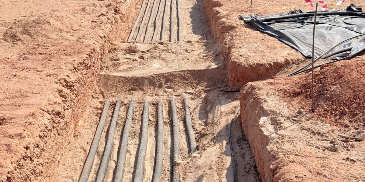
It is common practice to place the native soil back into a cable trench on top of the backfill containing the high voltage power cables. However, if the native soil has naturally high thermal resistivity or it will have from being prone to drying out then a controlled backfill with lower resistivity is used. Obviously if the thermal resistivity of the controlled backfill is lower than the native soil then an increase in the current ratings of the cables will occur.
How to model cables in backfill
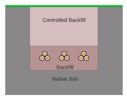
Figure 1 depicts a cable arrangement with three circuits of single core cables installed inside a thermal backfill with a controlled backfill added on top.
Figure 1. Cable laying arrangement with backfill and controlled backfill on top
The Standard IEC 60287-1-1 includes the equations for calculating current ratings only for a single backfill surrounding the cables but cannot be used to determine the effects of a controlled backfill on the current rating of the cables. For this situation a numerical algorithm based on the Finite Element Method (FEM) must be used. For further information refer to our article which explains this algorithm.
The cable being modelled
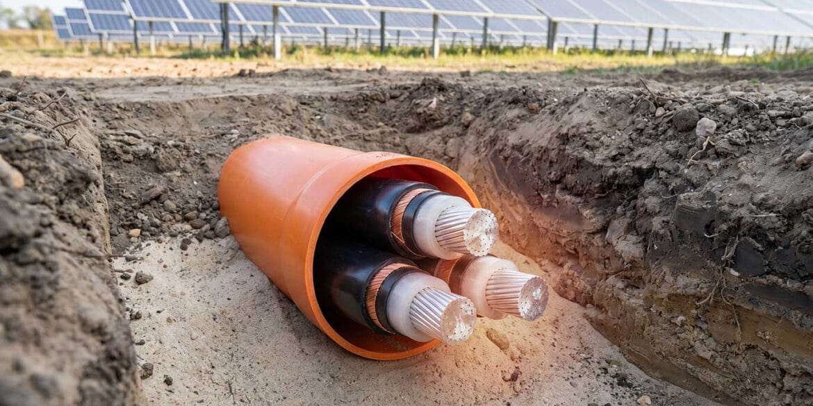
A parametric study has been performed using FEM to calculate the current rating of the cables due to the variation of the thermal resistivity of the controlled backfill. The study involves three circuits, each consisting of 500 mm2 single core cables. The cable model is shown in Figure 2.
Figure 2. Software model of 500 mm2 single core cables
Finite element method modelling
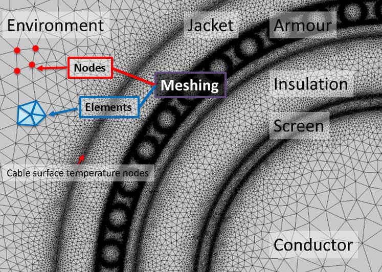
Multiple three-phase cable circuits were modelled as installed in a backfill centered at a depth of 1 m with a thermal resistivity of 0.5 K.m/W. The backfill height was 0.5 m and width was 0.7 m. The physical layout of the model along with the FEM meshing is depicted in Figure 3.
Figure 3. FEM model of the cables arrangement and buried installation
All the area inside the model in the image above needs to be meshed; which means subdividing all the components of the model including the cables and separate soil areas into elements. Each element has defined thermal properties and may have many elements which lie inside of it.
Results of the calculations
The study was conducted for the following conditions:
For each of the controlled backfill thermal resistivities, the native soil thermal resistivity was varied from 0.5 K.m/W to 4 K.m/W. Figure 4 shows current rating of the hottest (centre) circuit, for the various controlled backfill resistivities.
Figure 4. Current rating of cables vs native soil thermal resistivity for various control backfills
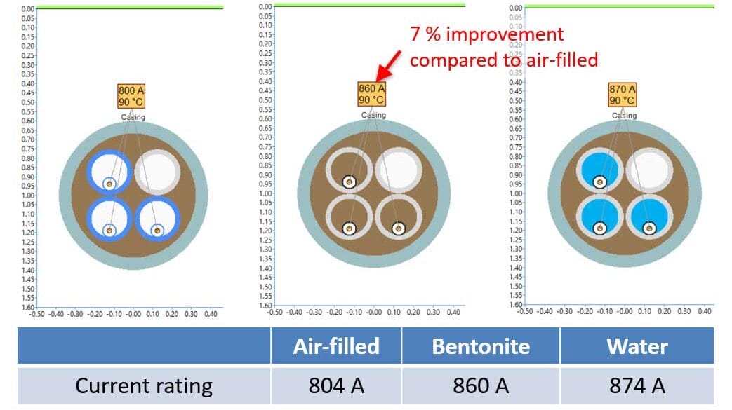
As expected, the results show that when the controlled backfill resistivity decreases, the current rating of the cables conversely will increase. The current rating of the cables improved up to 39.6% when the controlled backfill resistivity was changed from having no effect (same as the native soil of 4 K.m/W) down to 0.5 K.m/W. When the native soil resistivity is 4 K.m/W, the backfill resistivity is 0.5 K.m/W and the controlled backfill resistivity is 1 K.m/W, the improvement in current rating is 21.95%.
In conclusion a controlled backfill which has a better thermal resistivity than the native soil can be used to significantly improved the current rating of buried cables.
References
Leon, F.; Anders, G.J. “Effects of Backfilling on Cable Ampacity Analysed with the Finite Element Method” IEEE Transactions 2008.
Cable HV Software
Custom cable ratings for a wide range of installation conditions.
Dynamic cyclic rating of buried cables under daily load profiles. Worked five-feeder example, IEC 60853 basis, soil dry-out, emergency ratings, and FAQs
Finite element method (FEM) HV cable ampacity calculations benchmarked against CIGRE TB 963 and IEC 60287 to confirm accurate high-voltage cable ratings.
Explore HDD cable ampacity, soil dry out, water table effects, and duct behaviour. Model these conditions using electrical load calculation software for reliable ratings.
Prevent solar PV cable overheating with proper trench design. Learn how cable spacing, soil thermal resistivity, and backfill impact ampacity. Case study included.
Print this article:
Print
Print this article:
[printfriendly current='yes']
Cable HV Software
Custom cable ratings for a wide range of installation conditions.