What are waveform cables and where are they used?
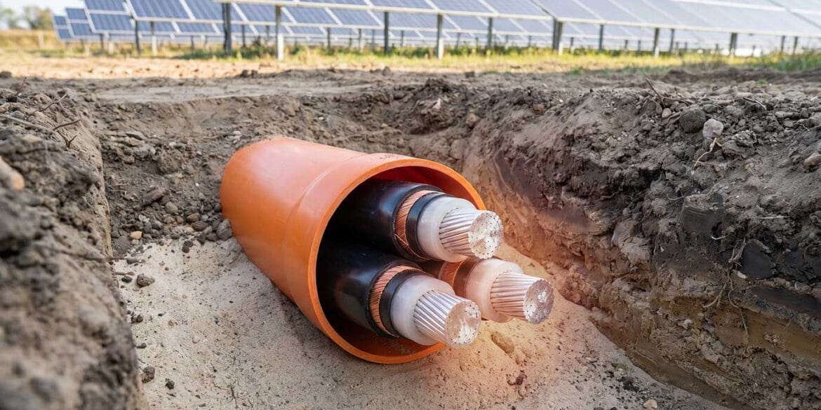
Waveform cables are commonly used in the United Kingdom (UK) for low voltage power networks. The term waveform refers to the way the neutral/earth wires are laid around the cores/bedding. Using this configuration enables the neutral/earth wires to be opened so a connection can be made to the conductors anywhere along its length. These cables are multicore cables with a typical voltage rating of 600/1000 V with standard conductor sizes ranging from 35 mm2 to 300 mm2. Waveform cables are usually insulated using XLPE materials and are sheathed using PVC. These types of cables are suitable for common installation configurations such as unenclosed in air, buried underground or submerged in water, indoor and in cable ducts.
Construction of 3- and 4-core waveform cables
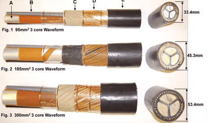
3-core waveform cable is shown in Figure 1 where the following letters denote:
- Aluminium conductors – sector shaped
- XLPE insulation
- Rubber bedding layer
- Copper neutral/earth wires
- PVC oversheath
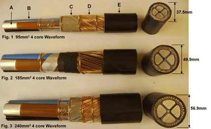
4-core waveform cable is shown in Figure 2 where the following letters denote:
- Aluminium conductors – sector shaped
- XLPE Insulation
- Rubber bedding layer
- Copper neutral/earth wires
- PVC oversheath
How to model waveform cables
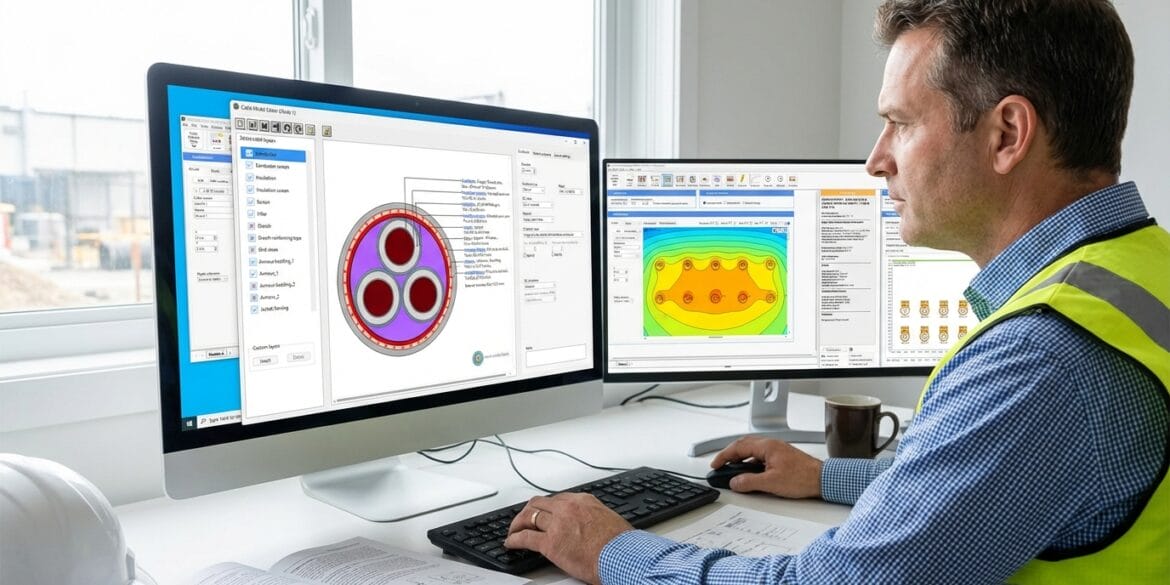
A waveform cable can be modelled diagrammatically by hand and equations can be used to calculate the current carrying capacity of these cables. Alternatively, Cable HVTM software can be used to expedite the process and for better accuracy.
To determine the cable current rating the construction of the waveform cable including the material types and the thicknesses of the layers needs to be known.
The manufacturer datasheet provides the waveform cable construction details required and a cable model is built to match in the editor window of Cable HVTM software.
The waveform cable construction data for various cable sizes is outlined in Table 1.
| Solid aluminium conductor size | |||||||
|---|---|---|---|---|---|---|---|
| 35 mm² | 70 mm² | 95 mm² | 120 mm² | 185 mm² | 240 mm² | 300 mm² | |
| Layer | Value | ||||||
|
Insulation: - Material - Temperature Limit - Thickness (mm) |
XPLE 90ᵒC 0.9 |
XPLE 90ᵒC 1.1 |
XPLE 90ᵒC 1.1 |
XPLE 90ᵒC 1.2 |
XPLE 90ᵒC 1.6 |
XPLE 90ᵒC 1.7 |
XPLE 90ᵒC 1.8 |
|
Filling: - Material - Thickness (mm) |
Rubber 1.15 |
Rubber 0.1 |
Rubber 0.1 |
Rubber 0.1 |
Rubber 0.1 |
Rubber 0.1 |
Rubber 0.1 |
|
Concentric Neutral/Earth Conductor: - Material - Temperature Limit - Nom. Diameter Of Wires - No. Of Wires |
Copper 90ᵒC 1.04 26 |
Copper 90ᵒC 1.85 16 |
Copper 90ᵒC 1.85 22 |
Copper 90ᵒC 1.85 28 |
Copper 90ᵒC 1.85 41 |
Copper 90ᵒC 1.85 41 |
Copper 90ᵒC 1.85 41 |
|
Sheath: - Material - Thickness (mm) |
PVC 1.8 |
PVC 1.9 |
PVC 2.1 |
PVC 2.2 |
PVC 2.5 |
PVC 2.7 |
PVC 2.8 |
| Approx. Overall Diameter (mm) | 26.3 | 30.5 | 33.4 | 35.9 | 45.3 | 51.2 | 53.4 |
Current rating calculation results
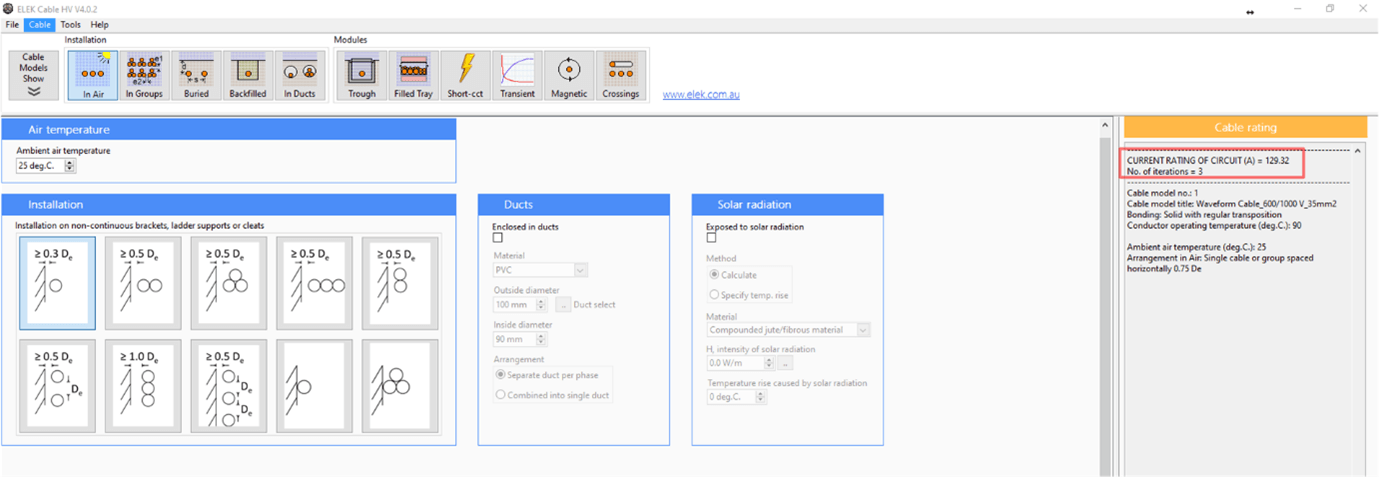
After the cable model files were created the current rating for various installation conditions could be investigated using the software. For example, as can be seen from Figure 3 for a 35 mm² cable the maximum permissible current rating is 129 A for the unenclosed in air case.
In Table 2, the results for all the cables sizes and their installation conditions are presented. The cables were modelled based on standard conditions as follows:
- Maximum conductor temperature 90°C.
- Ambient air temperature 25°C, ground temperature 15°C.
- Depth of burial 0.5 m and thermal resistance of soil 1.2°C m/W.
| Max. permissible current rating (A) | |||
|---|---|---|---|
| Installation configuration | |||
| Cable size (mm²) | Buried | Duct | In Air |
| 35 | 138 | 109 | 129 |
| 70 | 210 | 168 | 209 |
| 95 | 251 | 204 | 255 |
| 120 | 285 | 234 | 296 |
| 185 | 362 | 305 | 390 |
| 240 | 420 | 358 | 462 |
| 300 | 475 | 406 | 532 |
When comparing the cables in terms of cable size, larger cable sizes are able to carrying larger currents. Generally, in-air cables perform the best in terms of current carrying capacity as the heat dissipated from the cable is unrestricted allowing the cable to carry its maximum current for its temperature rating. Cables contained in ducts performed the worst as the heat dissipation from the cables is restricted within the enclosure reducing its current carrying capacity to approximately 80% of its unenclosed equivalent.
Try our High Voltage Cable Ratings Calculations Software to IEC 60287 for free.
Final words on waveform cable modelling
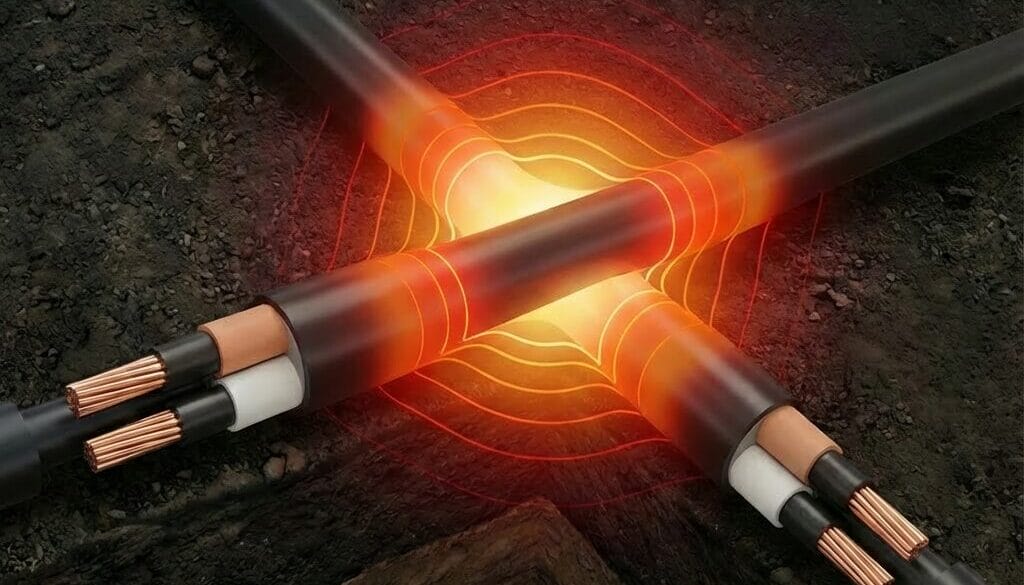
Waveform cables are ubiquitous for low voltage power network reticulation within the UK. The wave formation of the neutral /earth wires assists in cable stripping when the jointer accesses the phase conductors. The standard construction of waveform cables lends itself well to software modelling and one can easily calculate their current rating for various conductor sizes or specific installation conditions.
References
- Cable HVTM Website: https://elek.com/electrical-software/elek-cable-high-voltage/