What is voltage rise?
Voltage rise occurs in solar PV systems on the AC side between the power inverters and the network connection when power flows from the inverter back into the network.
Maximum limits for voltage rise are in place to avoid excessive voltages within the consumers installation and help reduce the occurrence of overvoltage protection trips on the inverters.
The limits set by the Standards for voltage rise are lower than for voltage drop since the power system normally operates above its nominal value and so there is less tolerance. For example, the nominal voltage level in Australia is 230 V (-6 %, +10%) however the average (normal) system operating voltage is around 240 V.
You can calculate the voltage rise by hand and using Cable Pro Web Software.
What are the voltage rise requirements?
There is an Australian Standard and there are state regulations covering the requirements and the limits for voltage rise.
The most widely-used limit in Australia is set by the AS/NZS 4777.1 – the overall voltage rise from the point of supply to the inverter AC terminals (grid-interactive port) shall not exceed 2% of the nominal voltage at the point of supply. Certain States in Australia (particularly NSW) also have specific requirements in their ‘Service & Installation Rules (SIR)’.
Table 1 summarises the voltage rise limits across Australia.
Table 1 – Voltage rise limits across Australia
| Document | Requirements | Special consideration |
|---|---|---|
| AS/NZS 4777.1 |
Clause 3.3: From the point of supply to the inverter a.c. terminals, the overall voltage rise < 2% |
N/A |
| NSW SIR: 2019 |
Clause 8.6.13: Service mains: < 1% Consumers mains: < 1% MSB <> Inverter (submains and final subcircuit): < 1% |
Clause 8.6.13.1: up to 2 % voltage rise may be permitted on any one component, if the sum of voltage rise on the remaining two components is less than or equal to 1 %. |
| VIC SIR: 2019 |
Clause 6.9.4.15: Voltage rise from the Inverter terminals to the point of supply shall comply with requirements of AS/NZS 4777.1. |
N/A |
|
QLD QECM1: 2018 SA SIR: 2017 WA ER2: 2014 |
Not mentioned | N/A |
1 QECM: Queensland Electricity Connection Manual
2 ER: Electrical Requirements
How to calculate voltage rise
Voltage rise is not different to voltage drop calculations. Two methods, the simple and the accurate methods are discussed below. The simple method is covered in AS/NZS 3000:2018 Appendix C4. The accurate method is covered in AS/NZS 3008.1:2017 Sections 4.4 and 4.5.
1 Simplified voltage rise calculation
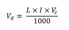
The basic formula for this method is:


2 Accurate voltage rise calculation
In the accurate method, resistance and reactance of a selected conductor size will be firstly obtained from Table 30 – 39 in AS/NZS 3008.1:2017 with reference to the conductor operating temperature. Formulas in AS/NZS 3008.1:2017 Section 4.5 are then applied with consideration of power factor to calculate the voltage rise accurately.
Cable Pro Web software uses this accurate voltage rise calculation method.
The accurate formula to calculate the voltage rise are shown below:
- For a single-phase system:

- For a three-phase system:


Power factor of load will affect the voltage rise significantly, especially for larger size conductors of which the reactance is relatively large.
When the cable size is known or anticipated, resistance Rc. and reactance Xc. will be obtained from Table 30 – 39 in AS/NZS 3008.1:2017 with reference to the conductor operating temperature since resistance is temperature dependant.
Conductor operating temperature is calculated by the following equation:


The accurate method based on the power factor of the load, the resistance and reactance of the conductor and conductor operating temperature will result in smaller cable sizes when compared with the simple method as will be demonstrated in the next section.
Example calculations - by hand and using software
This example from Standard AS/NZS 4777.1 is for an installation with a 400 V three-phase supply, a 30 metre consumer mains length, 60 metre final sub-circuit length to the three-phase inverter and only the main switchboard for connections.
It is necessary to select suitable cable sizes for the complete installation based on requirements for current-carrying capacity and voltage rise. For this example, two segments are considered: the consumer mains (existing installation) and the final sub-circuit to the inverter (new installation). Refer to Figure 1.
Method 1 - Simplified voltage rise by hand calculation
- Current-carrying capacity requirement
The required minimum current-carrying capacity for cables in the installation is determined based on the rated current of the inverters. The current rating for the 3 phase, 30 kVA inverter equates to a current rating of 43.35 A per phase.
To satisfy this current rating, a 6 mm2 conductor size with current-carrying capacity of 45 A is selected for both consumers mains and final subcircuit. This rating is based on three single-core thermoplastic copper cables enclosed within an underground wiring enclosure, as per AS/NZS 3008.1.1:2017, Table 7, Column 24.
- Voltage rise requirement
The overall voltage drop combining the consumer mains and the final sub-circuit to the inverter must not exceed 2 % per the AS/NZS 4777.1. For the three phase 400 V system this equates to an overall voltage rise of 8 V. The results of conductor size based on voltage rise requirement are shown in Table 2.
Table 2 – Voltage rise and min. conductor size results – Simple method
| Voltage rise | Conductor size | |
|---|---|---|
| Consumers mains | 3.16 V (0.79%) | 16 mm2 |
| Final subcircuit | 4.03 V (1.01%) | 25 mm2 |
Method 2 – Accurate voltage rise calculation using software
The results of minimum conductor sizes by method 2 are shown in Table 3.
Table 3 – Voltage rise and min. conductor size results – Accurate method
| Current-carrying capacity | Voltage rise | Conductor size | |
|---|---|---|---|
| Consumers mains | 101 A (> 43.35 A) | 2.42 V (0.60%) | 16 mm2 |
| Final subcircuit | 101 A (> 43.35 A) | 4.83 V (1.21%) | 16 mm2 |
Comparing the results for Tables 2 and 3 it is shown that the accurate voltage rise method results in a smaller cable size for the final subcircuit.


