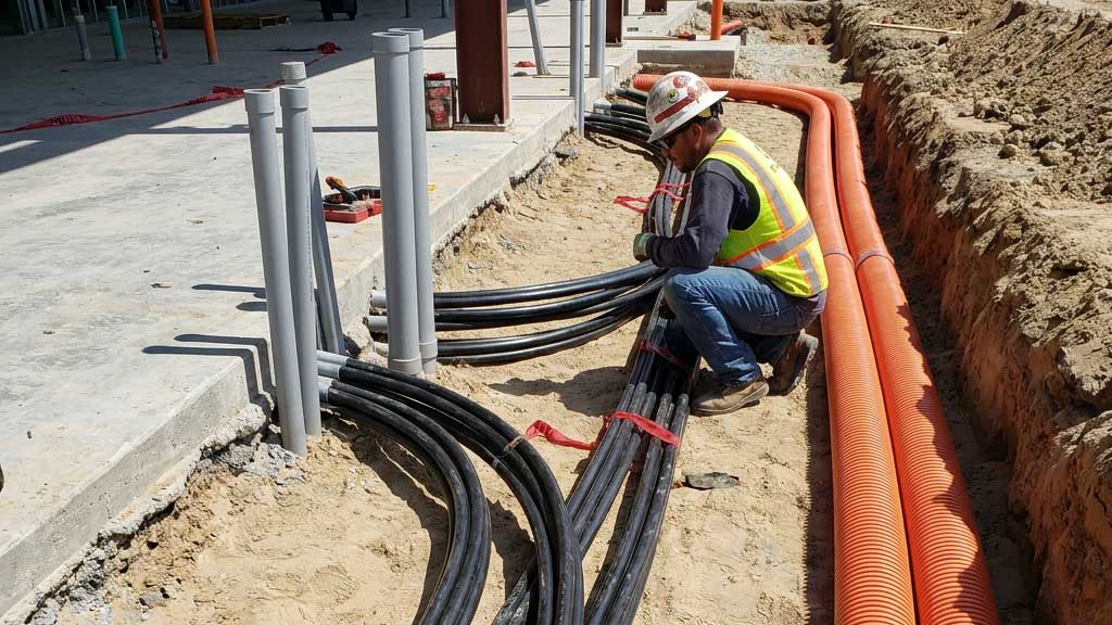
Checks before pulling cables
Prior to installing cables it is recommended that the route be inspected in order to:
- Avoid bends and pulling tensions that exceed the limits of the cables.
- Avoid clearance issues and jamming of the cables inside conduits.
- Tell you which direction of pull (forward or reverse) will be the best.
- Assist with placement and pulling force requirements for winching or push/pull machinery.
What is cable pulling tension?
Tension builds in cable pulls. In straight sections, it is added from one section to the next. In bends, incoming tension is a multiplier.
Cable pulling tension is the main parameter to be evaluated when assessing any cable installation, and knowledge of the pulling tension is essential to plan the cable laying and to assess the suitability of the cable design, route design, and installation methodologies.
The highest tension is at the end of the pull however, this may not be the case when there is a significant downhill section or a Push/Pull device in the pull. Tension is not multiplied when the cable is pulled around a bend through free-turning sheaths or rollers.
The tension required to pull cables can change significantly depending on the pulling direction. In general lower pulling tensions are encountered when feeding the cables into the end of a duct run with the largest number of bends or when cables are fed into the uphill side of a cable run.
According to a survey [ref. 2] the “average” maximum pulling lengths are 850 m in urban areas and 1185 m in rural areas. The absolute maximum reported lengths of pulls were 2200 m for urban areas and 3700 m for rural areas, but these required the use of highly specialised equipment and techniques for a successful pull.
Detailed pulling studies are required before finalisation of the cable route.
You can use Cable Pro Web software for accurate cable pulling tension calculations.
Maximum allowable cable tension
Maximum permissible tension of a cable is determined by its construction and is specified by the manufacturer.
Several equations [ref. 1] for estimating maximum allowable cable pulling tension are available, which can be used in the absence of more accurate data from the manufacturer.
The following equation is for maximum pulling tension based on pulling by the conductor, but there are other equations for pulling by a basket-weave grip over the cable outer jacket.

The maximum nominal pulling tension that a single-core cable can withstand is rated to be 22,250N. Due to the unevenly distributed forces of multicore cables when bending, this rating becomes 44,500N for a three-core cable [ref. 1].
What is cable sidewall pressure?
Sidewall pressure measures the normal force pushing a cable against the conduit wall in a conduit bend. Sidewall pressure depends on the tension coming out of the bend and the radius of the bend. Sidewall pressure is specific to each bend.
If there are no bends in the pull, there are no sidewall pressures.
Maximum allowable sidewall pressure
For single conductors, multiple conductors, triplexed power, and multi-conductor control or power cables, the Maximum Allowable Sidewall Pressure (MASP) is between 4380 N/m to 7300 N/m of bend radius based on the material of the cable.
Instrumentation cables have MASP ranging from 4380 N/m to 7300 N/m of bend radius, which relies on the construction and material of the cable.
Armoured cables have a MASP of typically 4380 N/m of bend radius or lower.

Calculating tension and sidewall pressure
There are various complicated equations used for calculating the tension and sidewall pressures for the following section types of a cable run:
- Straight or horizontal.
- Slope up/down.
- Horizontal bend.
- Downward or upward bends.
- Large radius bends.
- Rollers
- Push/pull machines.
Calculating cable clearance and jamming ratio
Where more than two cables are pulled simultaneously into a conduit, it is essential to calculate the cable clearance and jamming ratio. This will help to ensure the cables do not get stuck inside the conduit along the route.


Tension from pulling cable off the drum
Reel back tension is the force required to pull the cable off the reel. The tension required to pull the cable from a reel will depend on the cable size, weight of the first lap of the cable on the reel, the stiffness of the cable, and the type and condition of the reel payoff stand used. The tension force for pulling a cable off the reel in a horizontal position can be approximated using the following equation:

Correctly unwinding cable from the drum
When unwinding or winding on power cables from or to a cable reel/drum the top figures below show the correct methods and the bottom figures show approaches to be avoided.

Example pulling tension calculation:
Cable Pro Web software was used for performing the following calculations.
The cables are 3 x single core, Cu 500 mm2, XLPE/PVC with specifications as follows:
Overall diameter = 37 mm
Weight = 491 kg/100 m
Maximum permissible tension per cable = 10.6 kN
Maximum sidewall pressure = 1450 kg/m
The 3 cables will be installed inside a 125 mm diameter conduit.

Results
Pulling from either direction will not result in tension limit or sidewall pressure limit being exceeded.
Pulling from Location H requires a 20 % lower pulling force than pulling from Location A.
Use of a pulling lubricant results in a 67 % decrease in total tension.
Pulling from Location A:
Coefficient of friction = 0.5, dry 125 mm conduit.
| Location | Tension (N) | Sidewall pressure (N/m) |
|---|---|---|
| A | 0 | 0 |
| B | 1497 | 0 |
| C | 2233 | 78 |
| D | 2757 | 0 |
| E | 6127 | 214 |
| F | 6875 | 0 |
| G | 8065 | 282 |
| H | 8439 | 0 |
Coefficient of friction = 0.25, lubricated 125 mm conduit
| Location | Tension (N) | Sidewall pressure (N/m) |
|---|---|---|
| A | 0 | 0 |
| B | 748 | 0 |
| C | 916 | 32 |
| D | 1178 | 0 |
| E | 1760 | 61 |
| F | 2134 | 0 |
| G | 2606 | 91 |
| H | 2793 | 0 |
Pulling from Location H:
Coefficient of friction = 0.5, dry conduit.
| Location | Tension (N) | Sidewall pressure (N/m) |
|---|---|---|
| A | 0 | 0 |
| B | 374 | 0 |
| C | 569 | 20 |
| D | 1317 | 0 |
| E | 2933 | 102 |
| F | 3457 | 0 |
| G | 5153 | 180 |
| H | 6649 | 0 |
Coefficient of friction = 0.25, lubricated 125 mm conduit.
| Location | Tension (N) | Sidewall pressure (N/m) |
|---|---|---|
| A | 0 | 0 |
| B | 187 | 0 |
| C | 239 | 8 |
| D | 613 | 0 |
| E | 920 | 32 |
| F | 1182 | 0 |
| G | 1445 | 50 |
| H | 2193 | 0 |
References:
[1] IEEE Std. 1185-2019 Recommended practice for Cable Installation in Generating Stations and Industrial Facilities.
[2] CIGRE TB 889-2022 The installation of underground HV cable systems.