Table of Contents
Cable Connections for Offshore Wind
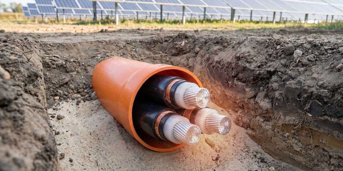
The use of high-voltage submarine power cables is on the rise due to a large extent to the rapid expansion of renewable energy sources such as offshore wind. For offshore wind farm applications, the submarine cables are terminated at the individual wind turbine or offshore switchgear/substation structures. Current losses from the submarine cables include conductor losses, sheath, screen, or armour losses, and dielectric losses are transferred through the outer layer of the cable into the environment. Along the underwater route to the offshore structures for the submarine cables, there are sections that provide better or worse thermal conditions which is a critical factor since the current rating of power cables is significantly affected by the thermal properties of the external environment.
Refer to our article named Submarine Power Cable Current Ratings for further information.
Submarine cables used for the connection of offshore structures are subject to varying installation conditions including inside J-tubes, burial in the seabed, and burial inside conduits. The current rating of the submarine power cables must be assessed (calculated) at all critical sections along the route. There are typically thermal bottlenecks along the underwater routes that include:
- The landfall, where the submarine cables may be routed through sea defense walls or where horizontal directional drilling is used that is deep (typically 30 meters below the surface).
- Through J-tubes or I-tubes of offshore platforms where the submarine cables are routed from the sea floor to atop the structure. An offshore substation or wind turbine platform typically has a number of J-tubes or I-tubes for the installation of multiple submarine cables. The air-filled section of the tube is particularly onerous.
- Where submarine soils have particularly high thermal resistivity. For example, submarine soils with exceptionally high thermal resistivities of up to 1.4 K.m/W (generally caused by the presence of high organic content) have been reported.
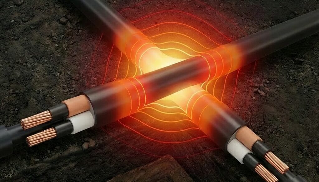
- Where the submarine cables will cross or be in close proximity to other heat sources such as other power cables or heated pipelines.
This article will focus on determining the current rating of the J-tube or the I-tube which very often is the section that is the worst-case.
It’s important to note that since these hot spots may only constitute a small proportion of the overall cable route it would not be economical to size the cable over the entire length on this basis. It is possible to use transition joints thereby allowing the increase of the cable size only for short sections.
What is a J-tube or I-tube?
To protect cables along their vertical trajectory from the seabed to the above-water structure the cables can be guided through a J-tube, an I-tube, or through the inside of a foundation via an opening.
A J-tube is a pipe that has a vertical bend and typically a bellmouth (which facilitates the pull-in of the cable) for cable entry taking the direction from vertical to horizontal near the seabed. The definition of a J-tube according to DNV-RP-0360 [2] is that it is “an open-ended, J-shaped section of a tube or pipe, attached internally or externally to a fixed offshore unit, for guiding and protection of a cable or cable assembly. The J-tube extends from a platform deck to and is inclusive of the bottom end near the seabed. J-tube supports are used to connect the J-tube to the supporting structure.”
An I-tube, on the other hand, ends vertically, and therefore the entire bend onto the seabed from vertically is made in free water near the entry of the I-tube which makes the cables more susceptible to scouring, abrasions, and higher dynamic loading. I-tubes require significantly larger distances between the end of the tube and the undisturbed seabed to facilitate cable installation.
Hang-offs are located at the top of the J-tube or I-tube, near the cable termination positions, that securely anchor the cables by the armour and electrically connect the cable armour to the earthing/grounding system of the structure.

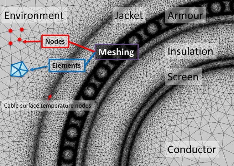
Thermal Model of J-tubes
The method developed to calculate the current rating of cables inside J-tubes is based on a comprehensive analytical heat transfer model. Below the sea level, the cables in the tube are cooled by the low water temperatures and the conductor temperature is almost constant. Nearer to the air section (still within the water-filled region) the temperatures start to increase; this is due to the longitudinal heat flow from the hotter section above. The hottest temperatures within the J-tube are observed inside the air-filled section. These are caused by the relatively high thermal resistivity of the air and the additional heating caused by the exposure to solar radiation. Owing to the design of the hang-off the J-tube is open to airflow at the top which allows convective heat transfer, however this flow is not circulating since the tube is blocked from airflow at the bottom due to the presence of the water inside the tube.
Temperature profiles are calculated for both one cable and three cables located in the J-tube. The thermal model includes conduction heat transfer in the cable and tube themselves as well as convection and radiation heat transfer that occurs between the outer cable surface and the inner tube walls and from outside of the tube walls surface. The heat rise caused by exposure to solar radiation can be considered.
Refer to Figure 1 above which depicts the thermal model of the J-tube or the I-tube
Cable Current Rating in J-tubes
As mentioned previously, the J-tube is typically the thermal bottleneck along the underwater routes for submarine power cables. The air-filled section of the tube is particularly onerous.
The main factors that affect the current ratings of cables in J-tubes are examined below.
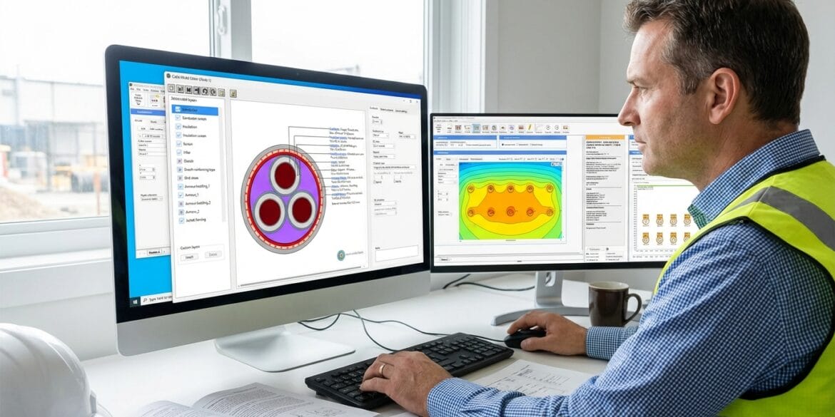
The current rating calculations were performed using ELEK Cable High Voltage Software.

Length of J-tube
The overall length of the air-filled section of the tube above the water level has a significant impact on the cable current rating.
The plot below shows as the length of the air-filled tube section increases the current rating of the cables decreases. It can be seen that the current rating of the 132 kV cable cores combined in a single tube (in trefoil – meaning for submarine 3-core cables) results in higher current ratings compared with separate tubes but that the rate of reduction in current rating due to tube length is similar; a reduction of 34 % when increasing the length from 5 up to 20 meters above the sea level.

The technical reasons why length affects the current rating are there are convective heat coefficients for the cable outer surface and the tube inner surface that are proportional to the length of the tube.
Diameter of J-tube
The diameter of the tube impacts the cable current rating. When modelling the J-tube it is assumed that it is closed at the top to the flow of air and this is important to note since it has an impact on how changing the tube diameter affects the heating of the cables inside (which may seem counter-intuitive).
The plot below shows that a smaller tube diameter causes lower conductor temperature and hence higher cable current ratings. The reason is the trapped air (non-convective) inside the tube has a high thermal resistance. For the cables in a narrow tube, the heat transfer coefficient of the outer wall of the J-tube is increased by approximately 19 % compared to the wide J-tube.

Environmental factors
Obviously, the ambient air temperature has a large impact on the cable current ratings which is similar to any other high-voltage cable installations.
Refer to our other article High Voltage Power Cable Ratings for further details.
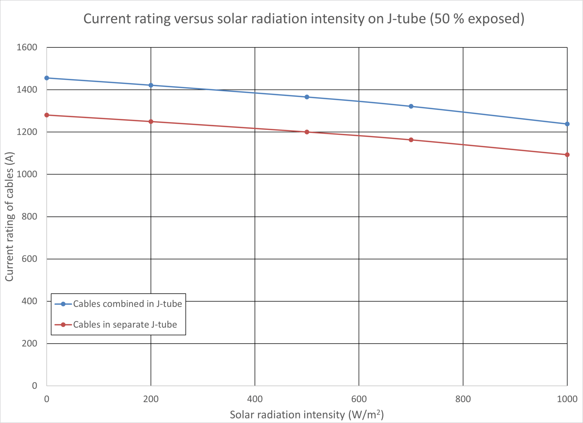
Solar radiation affects the cable current rating which depends on the intensity and also on the area of the tube exposed. Normally it is assumed that only part of the tube is exposed. The plot below shows that as solar radiation intensity increases the current rating of the cables reduces up to a 13.45 % reduction for an intensity of 1000 W/m2 where it has been assumed that 50 % of the tube’s outer surface is exposed. Typical values for exposure are 32% (Cress and Moltis (1991)) and 50% which assumes that half of the day the riser may be shaded from the sun.
Another significant environmental factor is the outside wind speed. The plot below shows that for the 132 kV power cables inside a J-tube, changing the wind speed from still air up to 10 m/s affected their current rating but around 10 %. Note that a typical design value of wind speed for overhead conductors is 3 m/s.

Additional Design Considerations
J-tubes and I-tubes are metal pipes and are generally used for offshore structures with fixed foundations although they can also be used for floating structures. Additional cable protection systems may be used to protect cables along other parts of the cable route which requires a separate design study based on the environmental conditions, cable jacket structure, and installation requirements.
A J-tube commonly has a bend from vertical which is between 30 and 45 degrees [1] however DNV-RP-0360 [2] provides typical angles of 45, 30, and 15 degrees depending upon the height above the seabed. A larger angle for the J-tube outlet provides better protection and more flexibility during installation. Smaller angles have the advantages of reducing sidewall pressure on the cables during pull-in and reducing the free span length (reducing the hydrodynamic loads acting on the cables).
The inner diameter of the J-tube or I-tube should not be less than 2.5 times the cable’s outer diameter to ensure sufficient heat dissipation of the cables and to avoid excessive pull-in forces [2]. The bending radius of the J-tube should not be less than 20 times the cable’s outer diameter.
When multiple tubes are used their horizontal separation between center lines should be at least 1 m and where multiple J-tubes are installed with bellmouths they should be spaced by at least 2 m. The spacing improves heat dissipation and reduces wave load.
The vertical length of a tube when made from multiple sections the separation distance between the separate sections should be ≥ 0.5 times the tube’s inner diameter (to facilitate convection) but not greater than 5 times the cable’s outer diameter (for smooth cable transitions).
References
[1] CIGRE TB 883 – Installation of submarine power cables
[2] DNV-RP-0360 Subsea power cables in shallow water. Recommended practice. Edition 2016-03 – Amended 2021-10.
[3] IEC 60287:2022 Electric Cables – Calculation of current rating