Table of Contents
Introduction
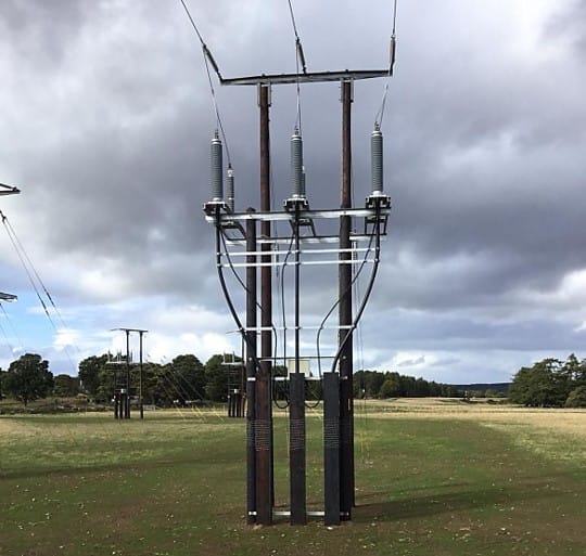
The solar farm earthing system is an important component of the renewable energy infrastructure. Its purpose is twofold: to safeguard personnel and equipment during electrical faults and lightning strikes, and to optimize the performance of the solar photovoltaic (PV) array. Solar farms cover large areas, thus their electrical earthing systems are potentially both expensive to build and maintain.
The key components of a solar farm earthing system include grounding conductors, grounding electrodes, and bonding connections. Often the metallic structures supporting the solar PV panels form a combined earthing system with these components.
Refer to this article for a detailed description of solar farm electrical and earthing systems.
The standards covering the design of utility-scale solar farms include very little about the earthing system design. There are several important factors affecting the performance, safety, and reliability of a solar farm earthing system including the area covered, soil electrical resistivity, fault current, as well as the earth grid conductor material which is the focus of this report.
Common conductor materials used for constructing solar PV earthing systems include copper, aluminium, zinc, and steel. The important differences between these materials include their electrical conductivity, permeability, corrosion resistance, mechanical durability, and cost. The difference in material properties produces vastly different performance of an earthing system, as we will see in this report.
ELEK SafeGrid Earthing Software™ was used for the modelling.
Selection of grid conductors and connections
According to IEEE Standard 80 [ref. 1], when evaluating the appropriate conductor material, size, or maximum allowable temperature limit, the following criteria of the grid conductors need to be met:
Have sufficient conductivity so that they will not cause significant local voltage differences.
Endure without melting or undergoing mechanical deterioration even in the harshest conditions of fault magnitude and fault duration.
Be mechanically strong and rugged to a high degree.
Maintain their function even when exposed to corrosion or physical abuse.
Choosing the most suitable conductor material for a solar PV farm earth grid depends on various factors, including budget, electrical performance requirements, and site-specific conditions. It’s essential to carefully evaluate the specific needs of the project, including factors such as soil conditions, expected corrosion levels, and budget constraints, to determine the optimal material for the earth grid conductor.
Table 1 below provides a comparison between common grid conductor materials used for solar PV farms.
Copper is often preferred for its superior electrical properties, while aluminum and galvanized steel are chosen for cost-effectiveness. Copper-clad steel can offer a balance between cost and performance.
Table 1: Comparison of different grid conductor materials
| Electrical conductivity | Corrosion resistance | Mechanical properties | Cost | Notes | |
|---|---|---|---|---|---|
| Copper | Excellent electrical conductivity, ensuring low resistance and efficient grounding. |
High corrosion resistance, making it suitable for long-term outdoor exposure.
Copper is cathodic with respect to other metals that are likely to be buried in the vicinity. |
High mechanical strength, reducing the risk of breakage during installation and maintenance. | Relatively expensive compared to other materials. |
Common material used for earthing systems.
Prone to theft due to its high scrap value. Heavyweight, which may increase transportation and installation costs. |
| Aluminium | Good electrical conductivity, Aluminium has approximately 61% of the electrical conductivity of copper. |
Lower corrosion resistance than copper, requiring additional protective measures.
Aluminium may corrode in certain soils and the layer of corroded aluminium is non-conductive. Aluminium is anodic (sacrificial) to many other metals including steel. |
Lightweight, leading to easier handling and reduced installation costs.
Lower mechanical strength compared to copper. |
Lower material cost compared to copper. |
Aluminium is rarely used for earthing systems.
It is not recommended to use aluminium conductors underground. |
| Galvanised steel | The electrical conductivity is not as good as copper and aluminium. | Good corrosion resistance, especially with proper galvanization. | High mechanical strength, making it suitable for use in harsh environments, | Cost-effective compared to copper and aluminium. |
Requires regular maintenance to prevent corrosion and ensure longevity.
Steel conductors have the potential to introduce electromagnetic interference (EMI) due to their magnetic properties. |
| Copper-clad and copper-plated steel | Higher electrical conductivity than galvanised and zinc-plated steel. | Enhanced corrosion resistance due to the copper cladding. | Combines the advantages of copper and steel. | Cheaper than copper or aluminium but more expensive than galvanised or zinc-plated steel. | Common material used for earthing systems. |
| Zinc-plated steel | The electrical conductivity is also not as good as copper and aluminium. | Good corrosion resistance, but not as good as galvanised steel. | High mechanical strength. | The cheapest material in this table. |
Software modelling and analysis
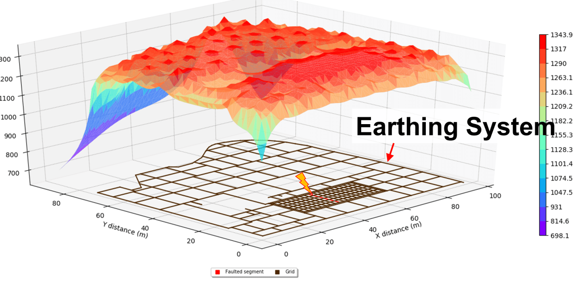
Software modelling of a typical solar farm with dimensions 300 m by 500 m was performed in order to demonstrate the effects of conductor material on grid performance. The simulations are performed for low resistivity and high resistivity soils of 200 Ohm.m and 2000 Ohm.m, respectively.
The different conductor materials used were:
Copper, annealed soft-drawn (100 % relative conductivity)
Aluminium, EC grade (61 % relative conductivity)
Steel,1020 (10.8 % relative conductivity)
Copper clad steel wire (40 % relative conductivity)
Zinc-coated steel rod (8.6 % relative conductivity)
The grid performance parameters that were recorded and compared includes the Grid Potential Rise (GPR), touch voltages, and step voltages.
The best grid performance was achieved using copper grid conductor since it has the the highest relative conductivity. Comparisons were made with respect to copper with the other conductor materials.
Table 1: Solar farm earthing system in 200 Ohm.m soil
| Material | Increase with respect to copper | ||
|---|---|---|---|
| Grid impedance | Touch voltage | Surface voltage | |
| Aluminium, EC grade (61% conductivity) | 2.21 % | 3.3 % | 1.3 % |
| Steel,1020 (10.8% conductivity) | 21.35 % | 29.05 % | 17.54 % |
| Copper clad steel wire (40% conductivity) | 5.15 % | 7.32 % | 2.99 % |
| Zinc-coated steel rod (8.6% conductivity) | 25.33 % | 34.11 % | 21.32 % |


Table 2: Solar farm earthing system in 2000 Ohm.m soil
| Material | Increase with respect to copper | ||
|---|---|---|---|
| Grid impedance | Touch voltage | Surface voltage | |
| Aluminium, EC grade (61% conductivity) | 0.25 % | 0.36 % | -0.08 % |
| Steel,1020 (10.8% conductivity) | 2.74 % | 4.53 % | 0.91 % |
| Copper clad steel wire (40% conductivity) | 0.55 % | 0.86 % | -0.02 % |
| Zinc-coated steel rod (8.6% conductivity) | 3.5 % | 5.75 % | 1.35 % |


Summary of the results
Grid impedance
The grid impedance increases in high resistivity soil. The conductor material significantly affects the grid impedance in low resistivity (200 Ω.m) soil but not in high resistivity (2000 Ω.m) soil.
Surface voltages
The maximum surface voltage that occurs during a fault is proportional to Grid impedance. In low resistivity soil the surface voltages for steel conductors are up to 21.32 % higher than for copper. However, in high resistivity the conductor material has little effect on the maximum surface voltages.Touch voltages
In low resistivity soils the maximum touch voltages were significantly increased by using steel conductors (by up to 34.11 %).
Conclusions
The earthing systems for solar PV farms are large and due to the sheer quantity of conductor required they can be expensive. Traditionally, copper has been the conductor material most widely used for earthing systems and for good reasons, because it has excellent electrical properties and durability. However, copper is also relatively expensive compared with other grid conductor materials and so there is a trend towards using materials besides copper to reduce material costs.
We have successfully demonstrated through computer modelling of an actual solar farm earthing system with different conductor material properties that:
- In low resistivity soils, earthing system performance is signficantly better using copper grid conductors.
- In high resistivity soils, grid conductor material has a negligible effect on grid performance. Therefore, potentially a significant reduction in cost may be achieved by using lower cost conductor materials. Note that corrosion resistance must also be considered based on the soil conditions.
References
[1] IEEE Std 80-2013 – IEEE Guide for Safety in AC Substation Grounding