Table of Contents
Introduction
The global offshore wind energy industry is rapidly growing; the market has grown by 36 % per year over the past decade bringing the total installed global capacity to 56 GW. Forecasts predict that the power transmitted by offshore wind energy to energy grids globally is expected to reach 380 GW by 2030 and 2000 GW by 2050 [ref. 7].
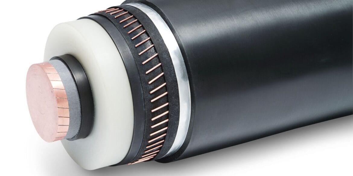
Submarine Cable Construction
")
Conductors
Submarine cable conductors are normally stranded copper, as copper has better conductance and corrosion resistance than aluminium. However, the cost difference between copper and aluminium is significant, leading to more aluminium conductors being used. Some submarine cable projects consist of copper and aluminium conductor sections, and multiple cable rating calculations may be required.
For deep-water applications, aluminium conductors are often used because these cables are lighter in weight, which is essential when laying or retrieving long lengths of cables.
Most XLPE insulated submarine cables use standard conductor areas (i.e., those sizes defined by Standard IEC 60228). Conductors for oil-filled and mass-impregnated non-draining (“MIND” cables for HVDC) cables may be non-standard sizes and are often made to meet a project’s needs. For example, non-standard conductor sizes of 790 and 1410 mm2 have been used, and up to 3500 mm2 are manufactured.
The conductor material selection (copper or aluminium) is based on the following considerations:
Electrical conductivity – Higher conductivity leads to a smaller conductor size for the same current-carrying capacity. Smaller conductors lead to less material used for the other cable layers, such as the insulation, screen, sheath or armour wires. A smaller cable size also increases cable length, which can be supported onto the installation vessel.
A special solution which reduces AC losses and capacitive charging currents for longer transmission is to operate the submarine cables at lower than the power system frequency (i.e. 16.7 Hz) however to date (as at 2025) there is only one project in existence which uses 20 Hz.
Mechanical strength and flexibility – Submarine cables must be capable of physically withstanding mechanical forces during installation and operation. Copper conductors have a slightly higher tensional strength allowance than aluminium conductors. (E.g. 20% higher for the same cross-section based on K=6 daN/mm2 for copper compared with K=5 daN/mm2 for Aluminium, but as mentioned, they are heavier, so this may create more stress).
Corrosion resistance – Corrosion is a significant problem for power cable installations in subsea environments. Copper is more resistant to corrosion than aluminium.
However, all cables are designed to stop water entry and transmission along the inside of the cable; hence, corrosion only occurs at a point of entry (damage).
Swelling agents between the conductor layers provide water tightness and avoid water ingress travelling along the inside of a submarine cable after damage from a fault.
Weight considerations – The weight of the cables themselves impacts the tensional force exerted on the cables during laying and recovery.
The weight of pure aluminium is about 1/3rd of that of pure copper. Therefore, for the same conductor area, the weight of aluminium is much less than copper. However, aluminium conductors’ current rating is less than copper’s.
Conductor Screen
Insulation
Metallic (Water Blocking) Sheath
Armour
Stainless steel wire armour, because it is non-magnetic, would avoid these losses. However, normal stainless steel grade 304 has extremely poor corrosion resistance in salt water, so it either must be galvanised or Stainless steel grade 316, which is a suitable marine grade. However, this grade is extremely expensive compared with normal Stainless steel grade 304, so it is often not selected.
Single-layer armour cable constructions or double-layer armour cables can be used. Typically, double-layer armoured cables are used for the ends of the circuits for extra tensional strength and mechanical protection.
Outer serving
Installation Conditions
")
Depth Of Burial
Thermal Resistivity Of Subsea Soils
Subsea soils usually have a relatively low thermal resistivity of 1 C.w/W or lower.
The thermal resistivity of soils depends on the soil base material, the dry density, distribution of grain size, the compaction, the moisture content and the content of organic materials.
The thermal resistivity of subsea soils does not vary much and due to being water saturated the thermal resistivity is quite low.
The Table below provides assumed thermal resistivity for common subsea soil types.
| Soil Type | Thermal Resistivity (C.m/W) | |
|---|---|---|
| Reference | [1] | [2] |
| Gravel | 0.55 | 0.33 - 0.5 |
| Sand | 0.2 - 0.59 | 0.4 - 0.67 |
| Clay/Slit | 1 - 2.5 | 0.56 - 1.11 |
IEC 60287-3-1 provides the following guidance based on standard practice by country outlined by the following table.
| Country | Description | Thermal Resistivity (C.m/W) |
|---|---|---|
| Finland | For submarine cables where the soil is completely saturated with water | 0.4 |
| Netherlands | Sub-soil water level near to cables | 0.5 |
| Sweden | For submarine cables where bottom is covered with sand Where nothing is known about the seafloor |
0.4 0.6 |
Note it is important to have actual and sufficient samples of subsea soils for a project along the route of installation. This is because there may be sections of soil containing high organic content and these have much higher thermal resistivity.
Submarine soils with exceptionally high thermal resistivities of up to 1.4 K.m/W (generally caused by the presence of high organic content) have been reported.
Thermal Resistivity Measurements
Ambient Temperature
Current Rating Calculations
")
Conclusion
References:
[1] CIGRE TB 610, “Offshore Generation Cable Connections”, 2015.
[2] CIGRE TB 640, “A guide for rating calculations of insulated cables”, 2015.
[3] Worzyk, T., “Submarine Power Cables – Design, Installation, Repair, Environmental Aspects.” Springer 2009.
[4] IEC 60287-3-1:2017 Electric cables – Calculation of the current rating – Part 3-1: Operating conditions – Site reference conditions.
[5] ASTM D5334-14 Standard Test Method for Determination of Thermal Conductivity of Soil and Soft Rock by Thermal Needle Probe Procedure.
[6] IEEE 442-2017 – IEEE Guide for Thermal Resistivity Measurements of Soils and Backfill Materials.
[7] Globaly Wind Energy Council, Global offshore wind report, 2022.
[8] CIGRE TB 883, “Installation of Submarine Power Cables”, 2022.