Table of Contents
Summary of Findings
Two validation studies were conducted to compare the ELEK Cable HV software model with reference results from CIGRE WG B1.72 for a cable system with 0.4 m phase spacing and single-point bonding.
The computed values from ELEK Cable HV show excellent agreement with the CIGRE benchmark data. The percentage differences were generally within 0.0022% for the emergency ratings and the transient temperatures.
Overall, deviations remain well below the acceptable ranges, demonstrating high accuracy and consistency between the CHV implementation and the CIGRE reference method.
The calculation method was validated for both steady-state and transient calculations, and minor deviations from published results are expected due to rounding.
Accurate Transient Cable Rating Calculations to IEC 60853
The current through a cable varies with the load. This causes the temperature of the cable and the surrounding media to vary. In short, as the load pattern changes, the cable takes time to heat up and cool down, thus allowing a higher peak current to flow through it. IEC 60853 provides a methodology for calculating the transient rating, in which the transient operation starts from an initial steady state (current rating I1 and conductor temperature θ1) and rises or falls to a second state (I2 and θ2). It uses the thermal resistance and capacitance network of the cable and its surroundings. This article compares the results from the transient module of Cable HVTM with those in CIGRE TB WG 1.72 [1].
For a detailed breakdown of the technical aspects and calculation methods, you can refer to this guide on the emergency and cyclic ratings of HV cables, which explains how thermal ladder networks and transient temperature responses determine permissible peak currents.
Introduction to ELEK Cable HV™ Software
ELEK Cable HV™ Software calculates high voltage cable ratings using IEC 60287 analytical equations, IEC 60853 [3] transient and cyclic methods, and finite element analysis for complex installations. Transient calculations are set up using the same cable and installation model as the steady-state work, so no separate thermal model needs to be built. Thermal capacitances, the ladder-network reduction, and the choice between the short- and long-duration circuits are all handled internally.
The software reports intermediate quantities rather than only the final current, which makes comparison at this depth possible. The transient solver reports the partial transients and the attainment factor and plots the conductor temperature curve over the load cycle.
For step-by-step instructions, see ELEK’s tutorial on how to use transient calculations in ELEK Cable HV software.
Validation Process for Transient Cable Rating Calculations
The case study 11 in the CIGRE TB deals with 3 scenarios
- Cables directly buried
- Cables buried in ducts
- Cables in the air
The validation followed four steps:
- Review the CIGRE document. Study the methodology, assumptions, and guidance points of Case Study 11, including the working group’s own commentary on ambiguities in IEC 60853 itself.
- Configure the model. Build the Case 0 cable from CIGRE TB 880 and the direct-buried flat installation of Case Study 11 in ELEK Cable HV™, matching every input value.
- Compare intermediate quantities. Apart from the results reported here, the thermal capacitances, the reduced ladder network, the transfer function coefficients, and the attainment factor were verified against the values in the brochure.
- Compare the three rating types. Verify the temperature response to a current step, the emergency rating, and the cyclic rating factor.
Cable Model
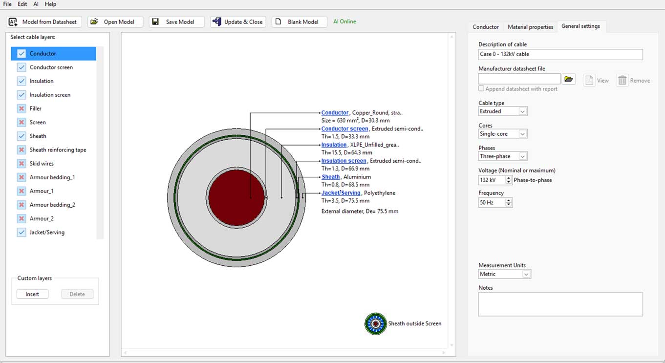
The cable is Case 0 from CIGRE TB 880 [2]: an extruded single-core 132 kV cable with a 630 mm² round stranded copper conductor, XLPE insulation with semi-conducting layers, a smooth aluminium sheath, and a PE oversheath.
Cable modelling can also be done automatically using AI; learn more in this live article on AI cable modelling for ampacity.
Cables Directly Buried
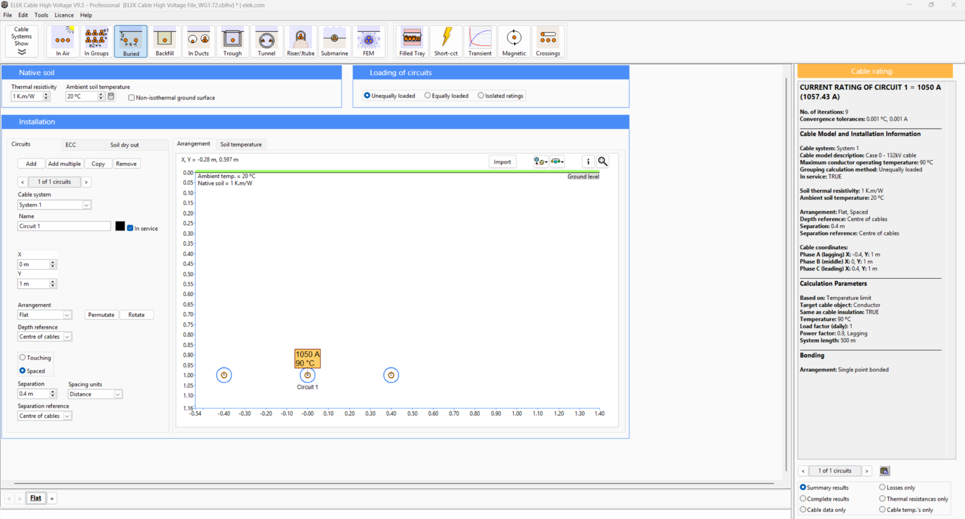
| Parameter | Value | Unit |
|---|---|---|
| Configuration | Flat, spaced | - |
| Depth to cable centre | 1 | m |
| Axial spacing | 0.4 | m |
| Bonding | Single point | - |
| Ambient ground temperature | 20 | °C |
| Soil thermal resistivity | 1 | K·m/W |
Comparison of Transient Temperature Results
The transient is calculated for t = 1 hour (3600 s), starting from an energised system carrying no load. The initial conductor temperature is not 20 °C but 20.5448 °C due to dielectric losses when the cable is energised and has long since reached steady state. Every subsequent temperature rise gets added to this reference level.
| Parameter | ELEK Cable HV™ | CIGRE WG B1.72 | Unit | Difference |
|---|---|---|---|---|
| Conductor temperature before correction | 39.929623264886 | 39.9296511367472 | °C | 7.0 × 10⁻⁵ % |
| Conductor temperature after correction | 37.1435757 | 37.1436 | °C | 0 |
The conductor’s electrical resistance varies with temperature, which affects losses. If the temperatures between hours differ significantly, the losses will also differ. The difference between conductor temperatures is approximately 3 °C because the ladder network was built with a conductor resistance evaluated at 90 °C, while the conductor is actually sitting near 37 °C. The iterative correction converges in five passes, with the conductor AC resistance falling from 3.8299 × 10⁻⁵ to 3.2795 × 10⁻⁵ Ω/m and the conductor losses from 42.83 to 36.67 W/m. If the resistances are not corrected, it will overestimate transient temperatures and, therefore, underestimate what a cable can actually carry.
| Without correction | With correction |
|---|---|
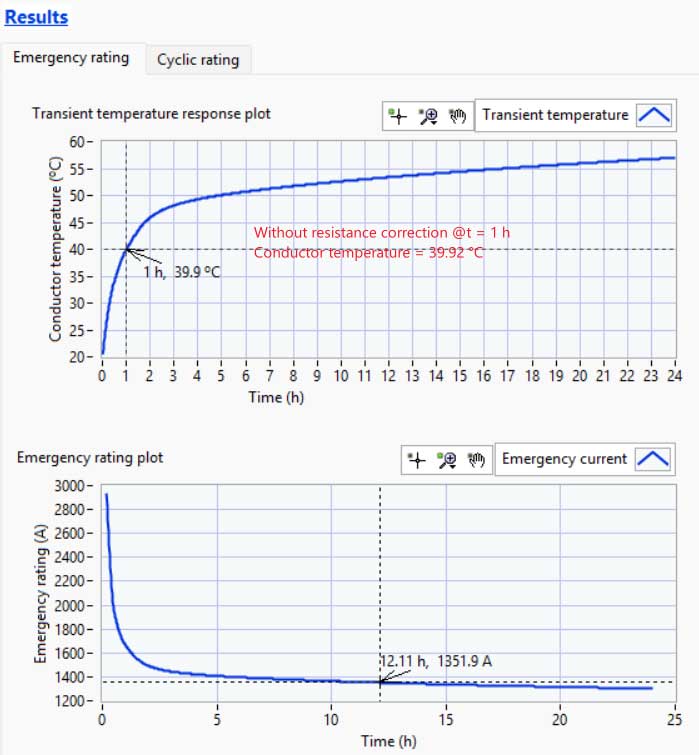 Fig. 3: Transient temperature and emergency rating plot without resistance correction
|
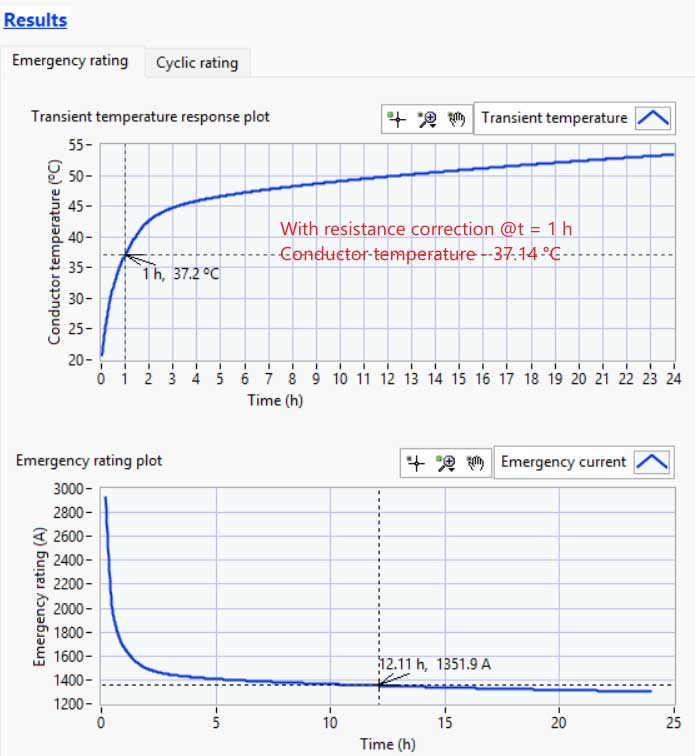 Fig. 4: Transient temperature and emergency rating plot with resistance correction
|
Comparison of Emergency Rating Results
The circuit is preloaded until the conductor temperature reaches 60 °C. In the event of a contingency, the conductor must be loaded without exceeding 90 °C.
The calculation needs three currents: the sustained rating IR at 90 °C, the pre-fault current I1 giving 60 °C, and the emergency current I2. The emergency current then comes from the Goldenberg formulation in IEC 60853-2 Section 8, which accounts for the change in conductor resistance between the two operating points.
| Parameter | ELEK Cable HV™ | CIGRE WG B1.72 | Unit | Difference |
|---|---|---|---|---|
| Current prior to the step I1 | 830.87 | 830.872876652964 | A | 0 |
| Complete temperature rise at 6 h | 30.172158807 | 30.1728262987258 | °C | 2.2 × 10⁻³ % |
| Emergency current I2 | 1396.565973262034 | 1396.5528469794 | A | 9.4 × 10⁻⁴ % |
The emergency current is 32% above the sustained rating and is available for six hours. That number determines whether a contingency requires load shedding.
Comparison of Cyclic Rating Results
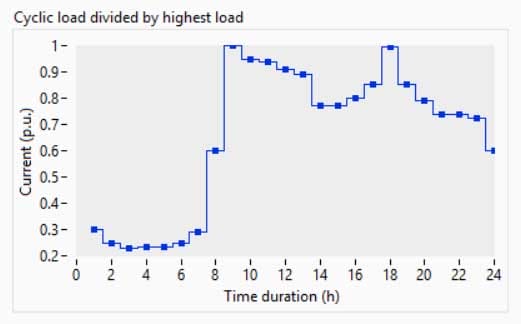
| Parameter | ELEK Cable HV™ | CIGRE WG B1.72 | Unit | Difference |
|---|---|---|---|---|
| Loss-load factor μ | 0.504332208333333 | 0.504332208333333 | - | 0 |
| Cyclic rating factor M | 1.2223395520 | 1.22233756457377 | - | 1.6 × 10⁻⁴ % |
| Permissible peak current | 1292.541409371 | 1292.53882429925 | A | 2.0 × 10⁻⁴ % |
Comparison of Conductor Temperature over Load Cycle
The peak temperature of the cycle occurs at 17.5 h, not at 8 h, where the load peaks. The load reaches its maximum at 8 h, but by 17 h, although it is not the highest load, the surrounding soil has absorbed the heat from a full day’s loading, so the second peak at 17 h occurs in a warmer thermal environment.
| CIGRE WG B1.72 | ELEK |
|---|---|
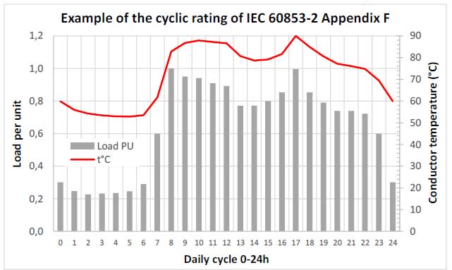 Fig. 6: Conductor Temperature over Load Cycle - CIGRE WG B 1.72
|
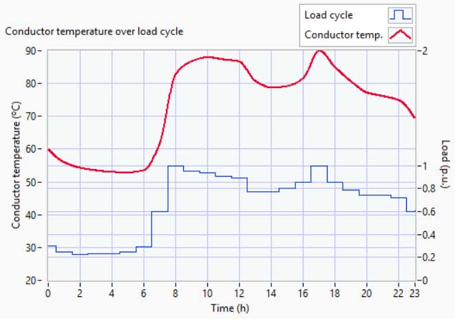 Fig. 7: Conductor Temperature over Load Cycle - ELEK Cable HV™
|
Takeaways
The following are the key takeaways.
Transient ratings unlock real capacity from the same cable. Against a sustained rating of 1057.43 A, the six-hour emergency rating is 1397 A (+32 %), and the permissible cyclic peak is 1293 A (+22 %). Sizing on the steady-state rating alone ignores the margin.
The correction for temperature-dependent conductor losses is not optional. The ladder network is built with resistances evaluated at 90 °C, but during a transient, the conductor is much cooler. The iterative correction drops the one-hour conductor temperature from 39.93 °C to 37.14 °C. Skipping the correction overestimates every transient temperature.
Cyclic rating factor. The resulting factor of 1.22 means the cyclic load can peak at 1292.5 A against a sustained rating of 1057.4 A. For a distribution feeder with a pronounced daily profile, ignoring the cyclic rating results in 22% of the capacity being unused.
Conclusions - ELEK Cable HV™ Successfully Validated
Every quantity in Case Study 11 was reproduced, from the individual thermal capacitances through to the cyclic rating factor. The largest relative deviation is 0.0022%, and most quantities agree to 9 or more decimal places.
References
[1] CIGRE WG B1.72. “Power Cable Rating Examples for Calculation Tool Verification – Additional Cases.” Case Study 11.
[2] CIGRE B1 Insulated Cables Technical Brochure. “Guidelines for the Rating Calculations of Insulated Cables.” Reference 880. September 2021.
[3] IEC 60287:2023 SER Series. Electric cables – ALL PARTS.
[4] IEC 60853-2:1989 + AMD1:2008. Calculation of the cyclic and emergency current rating of cables.