Overview
This engineering guide relates to the use of SafeGrid earthing design and analysis software to IEEE Std 80 and IEC 60479.
The principles contained within this Engineering Guide apply generally to the topic of electrical earthing and grounding.
Summary of recommendations
- When the soil model is high-on-low resistivity use rods which penetrate into the lower layer to reduce grid resistance.
- Use rods at the corners of the grids where step and touch potentials are largest.
- It is not economical to use rods where the bottom layer soil resistivity is higher than the top layer (low-on-high).

Earthing systems
This concept represents the prevailing practice used around the world.
Grid conductors and rods
In turn, when several electrodes, such as ground rods, are connected to each other and to all equipment neutrals, frames, and structures that are to be grounded, the result is essentially a grid arrangement of ground electrodes, regardless of the original objective.
Partly for this reason, some utilities depend on the use of a grid alone. However, under certain circumstances ground rods are of particular value.
Safe earthing systems
- If the magnitude of the fault current to be dissipated to the earth is high.
- The resistivity of the soil is high.
- The area over which the earth grid can be installed is small.
Use of earthing rods
- While horizontal (grid) conductors are most effective in reducing the danger of high step and touch voltages on the earth’s surface, provided that the grid is installed in a shallow depth, sufficiently long ground rods will stabilize the performance of such a combined system.
- Freezing or drying of upper soil layers could vary the soil resistivity with seasons, while the resistivity of lower soil layers remains nearly constant.
- Rods penetrating the lower resistivity soil are far more effective in dissipating fault currents whenever a two-layer or multilayer soil is encountered and the upper soil layer has higher resistivity than the lower layers.
- If the rods are installed predominately along the grid perimeter in high-on-low or uniform soil conditions, the rods will considerably reduce the steep increase of the surface gradient near the peripheral meshes.
SafeGrid Example – Use of earthing rods to improve safety
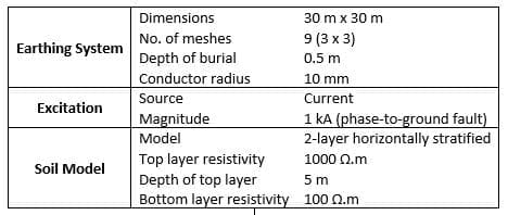
Earthing rods can offer a cost effective way of reducing grid resistance and greatly improving the safety of an earthing system. The following is a design example using the SafeGrid Earthing Software to demonstrate these principles.
Earth grid model
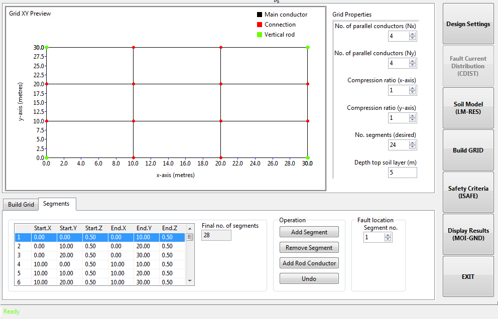
A simple earthing grid was built using the SafeGrid grid editor.
- More complex grids may be imported as a CAD (DXF) file.
- High on low soil resistivity model.
Results
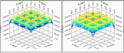
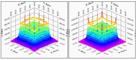
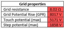
Without earthing rods
The following results were obtained from the simulations for the earthing system consisting only of horizontally buried conductors without earthing rods.
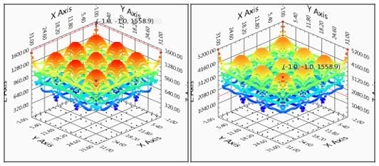
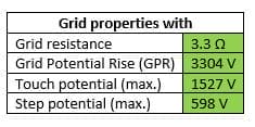
Earth rods installed at grid corners
The following results were obtained from the simulations for the earthing system consisting of both horizontally buried conductors and four (4) 10 m long earth rods installed at the corners.
Conclusions
From the simulations using SafeGrid software the following conclusions can be made.
The use of earthing rods at the corners of the grid to penetrate into the lower resistivity soil layer:
- Significantly reduces the grid resistance.
- Fault current is much more effectively dissipated away from the surface of the earth reducing surface potentials.
- Maximum step and touch potentials are significantly reduced.

