Table of Contents
Introduction
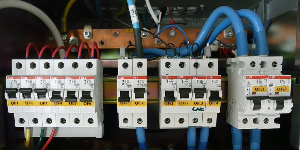
Miniature Circuit Breakers (MCBs) are crucial components in electrical engineering, protecting overcurrent in electrical circuits. Selecting the right type of MCB is essential to ensure electrical systems’ safety and efficiency. MCBs are categorised based on their tripping characteristics, represented by different device curves such as Z, B, C, K, and D. This article explores the various types of MCB device curves and offers guidance on selecting the right type for your application.
Types of MCB Device Curves
Type Z MCBs
Characteristics: Type Z MCBs have the most sensitive tripping characteristics, with a tripping range of 2 to 3 times the rated current (In).
Applications: Designed for sensitive equipment that can withstand only minimal currents above their rated levels before sustaining damage. It is commonly used in circuits containing highly sensitive electronic devices.
Use Case Example: Protecting sensitive measurement instruments or control circuits in laboratories.
Type B MCBs
Characteristics: Type B MCBs trip at 3 to 5 times the rated current. They provide a rapid response to short-circuits and moderate inrush currents.
Applications: Suitable for residential and light commercial installations with resistive loads or small inductive loads.
Use Case Example: Protecting lighting circuits, household outlets, and small electrical appliances.
Type C MCBs
Characteristics: Type C MCBs trip at 5 to 10 times the rated current. They are designed to handle higher inrush currents typically associated with inductive loads.
Applications: Ideal for commercial and industrial installations with moderate inductive loads.
Use Case Example: Protecting motors, air conditioners, and fluorescent lighting systems.
Type K MCBs
Characteristics: Type K MCBs trip at 8 to 12 times the rated current. They are specifically designed for circuits with significant inductive loads.
Applications: Suitable for industries where high inrush currents are common, such as in machinery and large motor applications.
Use Case Example: Protecting heavy-duty motors, transformers, and industrial machinery.
Type D MCBs
Characteristics: Type D MCBs have the highest tripping range, from 10 to 20 times the rated current. They are designed to handle very high inrush currents.
Applications: Used in environments with heavy inductive and capacitive loads, where substantial inrush currents are expected.
Use Case Example: Protecting large motors, X-ray machines, and welding equipment.

Selecting the Right Type of MCB
1. Identify the Load Type:
Understand the nature of the load the MCB will protect.
Resistive loads (e.g., lighting, heating) vs. inductive loads (e.g., motors, transformers).
2. Determine the Inrush Current:
Assess the starting or inrush current characteristics of the equipment.
Choose an MCB type that can handle the initial surge without tripping unnecessarily.
3. Match the MCB to the Application:
For sensitive electronic circuits, opt for Type Z.
For general residential use with moderate overcurrent protection, Type B is ideal.
For commercial applications with moderate inductive loads, go with Type C.
For industrial applications with considerable inductive loads, select Type K.
Type D is the best choice for heavy industrial applications with significant inrush currents.
4. Check the Breaking Capacity:
The breaking capacity must be greater than the highest prospective short-circuit current at the installation point. Common capacities include 6 kA, 10 kA, and 15 kA.
5. Consider the Standards:
Ensure the selected MCB complies with relevant standards and regulations for your specific application and region.
Conclusion
Selecting the appropriate MCB type is vital for the protection and longevity of electrical systems.
Understanding the characteristics and applications of different MCB device curves—Z, B, C, K, and D—enables engineers to make informed decisions for optimal safety and performance.
By considering the load type, inrush current, and specific application requirements, you can choose the right MCB to ensure reliable and efficient electrical circuit protection.
References
IEC 60898-1: Electrical Accessories – Circuit-breakers for overcurrent protection for household and similar installations
BS EN 60898-1: British Standard for Circuit-breakers for overcurrent protection for household and similar installations


