Design safe earthing systems for transmission towers
Background
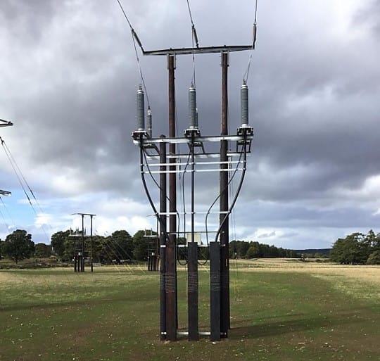
The purpose of transmission line grounding is to (a) provide adequate lightning performance of the line; and (b) effectively dissipate fault current avoiding the build-up of unsafe step and touch potentials around the tower base.
The tower earthing system is provided by an electrically interconnected system of conductors and rods, connectors, foundation and the local soil.
Individual tower earthing designs must consider the electrical performance of the line and the individual tower. Different tower earthing designs can occur from tower to tower due to the variation in parameters and conditions along the length of the line.
During a phase to earth fault, current flows back to the source via the overhead earth wires and through the earthing systems of the individual towers. Potential gradients which are expressed in terms of step and touch occur in the soil surrounding the towers need to be evaluated with respect to safety limits imposed by regulations and standards.
Touch and step potentials and the safety limit requirements around a transmission line tower need to be assessed as they can significantly affect the layout of a safe earthing system design.
Case 1 is an example from EPRI grounding system design guide [2].
Table 1 Case 1 -earthing parameters
Figure 1 Transmission tower earthing with single potential control ring.
Case 2 – Double potential control rings:
Table 2 Case 2 – earthing parameters
Figure 2 Transmission tower earthing with double potential control rings.
Methodology
Both case studies were modelled and analysed using SafeGrid™ earthing design software. Grid models were built using the integrated grid editor. However, 3D grids of any arbitrary configuration can also be built in CAD and imported as a DXF file. Common inputs for buried conductor internal resistance and inductance calculations are:
Table 3 Common inputs for conductor internal R+X
Results
The calculation results of the two case studies are given below. Step and touch potentials are calculated for up to 1 m and 5 m, respectively, from the perimeter set by the outside control ring.
Table 4 Calculation results for Case 1
Figure 3 Transmission tower earthing with double potential control rings
Figure 4 Touch potentials (V) in X-Y view – Case 1
Figure 5 Step potentials (V) in X-Y view – Case 1
Table 5 Calculation results for Case 2
Figure 6 Surface potentials (V) in 3D view – Case 2
Figure 7 Touch potentials (V) in X-Y view – Case 2
Figure 8 Step potentials (V) in X-Y view – Case 2
Tower footing resistance is much higher for Case 2 compared with Case 1 due to higher soil resistivity values.
Tower potential rise is similar for both cases (despite higher tower footing resistance for Case 2) due to lower fault current magnitude for Case 2.
Higher step and touch potentials occur for Case 2 than for Case 1.
The highest step and touch potentials occur at the edges of the outer control ring.
Safety criteria
The allowable safety criteria limits are calculated using SafeGrid™ in accordance with both IEEE Std-80 and IEC 60479.
Table 6 Common inputs for safety criteria calculations
Table 7 Step and touch potential limits to IEEE Std-80
Table 8 Step and touch potential limits to IEC 60479
Note that safety criteria limits calculated for IEC are less stringent than for IEEE when fault clearing time is less than 0.4 seconds.
Assessment of safety
Touch voltages
Generally for this situation the touch voltages which need to be assessed are for those areas which are within 1 m (reach) from the steel tower legs.
Figure 9 shows an X-Y plot of unsafe touch potentials. These are defined as touch potentials which exceed the safe limits given in Table 8 Step and touch potential limits to IEC 60479. Note the location of the four tower structure legs are highlighted by a 1 metre radius circle. Only touch potentials which exceed the safe limits and fall with this circle are unsafe. Therefore no unsafe touch voltages exist.
Figure 9 Touch voltages which exceed IEC safe limits – Case 1
Figure 10 Touch voltages which exceed IEC safe limits – Case 2
Step voltages
Since touch voltages are safe then it is expected that step voltages will also be safe. Since the calculated maximum step potential is 261.2 V (Figure not shown) which is less than the IEEE and IEC safety limits (348.5 V and 442.6 V respectively) then no unsafe step potentials exist.
Effects of adding vertical rods
Four vertical rods of 5 metres in length were included in the model for Case 2. The locations for the rods were at the location of the tower legs.
The expected reduction in tower footing resistance was not significant. The tower footing resistance for Case 2 was reduced from 12.48 Ohms to 11.66 Ohms. The tower potential rise was reduced from 2022 V down to 1888 V.
In both cases due to the soil consisting of a low on high soil model the addition of vertical rods will not be effective at reducing the tower footing resistance. Generally rods are only effective (economical) when the bottom layer soil resistivity is lower than the upper layer.
Conclusions
The assessment of safety related to the earthing of transmission towers is necessary however it is inherently complicated. Access to intuitive software which can accurately model the designs for various configurations and scenarios is essential.
References:
[1] SafeGrid™ – Earthing Design and Analysis software. [2] EPRI grounding system design guide. [3] IEC 60479 Effects of current on human beings and animals. [4] IEEE Std-80 Guide for safety in AC substation grounding.
SafeGrid Earthing Software
Easily design safe earthing systems in compliance with Standards.
Understand how software simulations enhance grid impedance tests, improving accuracy and efficiency in earthing system design and performance evaluation.
This report explains how to perform accurate earth fault current analysis for substations connected by cable transmission lines. Earth fault currents for simple cable and overhead transmission lines are explained first. Next, two case studies involving hybrid cable transmission lines are presented.
Copper is often preferred for its superior electrical properties, while aluminum and galvanized steel are chosen for cost-effectiveness. Copper-clad steel can offer a balance between cost and performance. This article demonstrates which option is best for different scenarios.
The technical guide explains the electrical systems, local WTG and combined earthing system design, touch and step voltage hazards, soil electrical resistivity measurements, earth fault currents, earthing system software modelling, and validation testing of earthing for wind farms.


 in X-Y view – Case 1")
 in X-Y view – Case 1")

 in 3D view – Case 2")
 in X-Y view – Case 2")
 in X-Y view – Case 2")