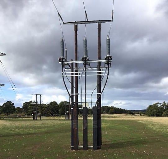
Why are fences around substations required?
Fences around substations are essential to keep people safe and most often, these fences are metallic, due to economics, which poses some earthing safety challenges. These metallic fences which are easily accessible to the public and personnel must be adequately earthed and the touch voltages on these fences during an electrical fault must not exceed safe limits.
For earthing modelling of a substation with a metal fence, to ensure safety, there are two important questions to answer:
- Should a metal substation fence be connected to the main earth grid?
- How should it be positioned with respect to the main earthing grid?
Fence positions and earthing arrangements
Multiple test cases were conducted using SafeGrid Earthing Software to find the best fence placement resulting in the safest (lowest) touch voltages.
Cases numbers where the fence is connected to the main grid, and:
- Fence is positioned inside the area of main grid.
- Fence is positioned on the boundary of the main grid.
- Fence is positioned outside but close to the boundary of the main grid.
- Fence is positioned outside but far away the boundary of the main grid.
The last case is where the fence is not connected to the main grid:
- Fence is positioned outside but far away the boundary of the main grid.
The earth grid and fence earthing models are given in the Appendix.
These test cases are consistent with those from Section 17.3 on page 102 of IEEE Std 80-2013. In all the above test cases the total length of the fence is the same.
The following common parameters apply:
Soil resistivity (ρ) = 60 Ω.m (uniform soil model)
Fault current (IG) = 5000 A
Fault duration (ts) = 0.5 s
Decrement factor (Df) = 1
Touch voltage limit = 242 V for a body mass of 70 kg per IEEEStd. 80 [1].
Safest fence earthing arrangement
The safety in terms of maximum touch voltage (on the fence) was tested for each of the cases and the results are summarised in the below table. Touch voltages were determined at 0.91 m away from the fence boundary (approximately an arms’ length).
Table 1. Test case results
| Case number | Fence connected to grid | Fence position to the grid | GPR (V) | Max. touch voltage (% of GPR) | Order of safety |
|---|---|---|---|---|---|
| 1 | Yes | Inside | 2968 | 8.16 | 1 |
| 2 | Yes | Above | 3150 | 7.68 | 2 |
| 3 | Yes | Outside | 3121 | 7.76 | 3 |
| 4 | Yes | Outside | 3302 | 7.33 | 4 |
| 5 | No | Outside | 4756 | 5.09 | 5 |
A 3D plot of touch voltages for the safest case 1 is shown in Figure 1. As can be seen the highest touch voltages occur along the outside perimeter of the grid, with the maximum values being at the corners.
To compare touch voltages for the five different cases a series of profiles are plotted in Figure 2.

The four cases 1-4 where the grid is connected to the fence all have significantly lower touch voltages compared with the last case 5 where the fence earth is not connected to the grid.
Case 1 where the fence is connected and positioned inside the perimeter of the main earth grid produces the lowest touch voltages and therefore is the safest.

Recommendations
The two important safety-related questions in the introduction have been answered. In general, it is better to bond the earth grid with the fence and to position the fence inside the earth grid.
Case 1 with the fence inside the grid perimeter is safest because when a person is in contact with the fence (while reaching) they are standing above the buried grid conductor and therefore the voltage at their feet will be nearer to the grid potential rise resulting in lowertouch voltages.
References
Appendix: Grid and Fence Diagrams
Case 1:

The fence is inside the grid and its borders are 0.91m away from the grid. The fence and grid are connected.
Case 2:

The fence and the grid approximately have the same area and run alongside each other.The fence and grid are connected.
Case 3:

The Grid is inside the fence and its borders are 0.91 m away from the fence borders.The fence and grid are connected.
Case 4:

Case 5: