Introduction
Testing of earthing systems enables confirmation of the design values and safe operation in the case of a fault condition according to the applicable safety standards and criteria.
Current injection testing is a methodology which facilitates comprehensive testing of buried earthing systems. Numerous important characteristics relating to an earth systems performance can be measured including:
- Grid Potential Rise.
- Ground/Earth Potential Rise.
- Voltage contours and transfer potentials.
- Touch and Step potentials.
- Current distribution in complex grounding systems.
Table of Contents
Earth resistance measurement
Fall of potential method
This earth resistance measurement is performed using the 4-pole method.
The following step-by-step procedure applies for performing the measurements:
- Place the test equipment as close as possible to the earth system under test. The distance should be no farther than 10 m away from the edge of the earth system.
- A set of two shorter leads are connected to the earth system under test. The point of attachment should be cleaned prior to connection.
- The current and potential leads and probes are taken in parallel away from the earth system along the test route. The current lead should be completely uncoiled from its reel and shall not cross the potential measurement lead.
- The remote injection electrode (rod cluster) shall be driven into the ground at a distance which is enough to be outside of the sphere of influence from the earth system under test. For a large earthing grid, the separation to the remote electrode should be at least 5 times the diagonal width of the grid. The nature of the 4-pole method permits the use of very long and different size cables without the need for resistance compensation. It is typically necessary to use multiple earth electrodes connected in parallel with each other to reduce the contact resistance of the remote earth electrode.
- The potential measurement probe is driven into the ground at a distance which is 80 % of the distance separation of the current electrode away from the earthing system under test. It should be at least 1 m away from the current electrode.
- The test equipment operator shall instruct engaged personnel and nearby persons to stand clear of the test leads and electrodes.A measurement shall be taken. If the measurement fluctuates then 10 sequential values are to be taken and an average value calculated.
- Having informed those remote from the test equipment that the current injection has ceased and that test leads have been disconnected, the potential electrode should be moved to a new location which is toward the earthing system and 10 % of the distance between the current electrode and the earthing system under test. The test is to be repeated such that measurements are obtained at 10 % intervals, ideally between the 80 % and 20 % distances (i.e. 7 readings, together with 2 additional readings at the 55 % and 65 % distances).
- The resistance measurement obtained should be plotted on a curve during the tests. The plotted values should follow the trend as per Figure 1. Any obvious outlier readings should be repeated.
- If the interpretation of the results using the slope method does not yield satisfactory results the series of tests shall be repeated using a new position for the current electrode, either farther away from the earthing system or in a different direction (if possible).
- Once an acceptable set of results is obtained the current electrode position should be noted for future reference.
 - Plot of distance from earth system versus measured resistance")
Additional test – 90 ° fall of potential method
Wherever practical and if time permits or if deemed necessary due to perceived problems with the previous data from the in-line tests, this additional test shall be carried out.
With this test approach the current electrode is left in its current position and the potential electrode along with the associated cable is withdrawn back to the edge of the earthing system under test. The potential electrode is then run out at a 90˚ angle to the current electrode for approximately 20 % of the current electrode separation from the earthing system. The tests are repeated at distances of 40 %, 60 %, 80 % etc., if practicable, and the measured resistance values plotted versus separation (distance).
The type of plot shown in Figure 2 is used for deriving the lowest possible value of resistance for the earth system under test and is used in conjunction with the slope method/in-line test to increase confidence in the results.
 - Plot of distance from earth system versus measured resistance")
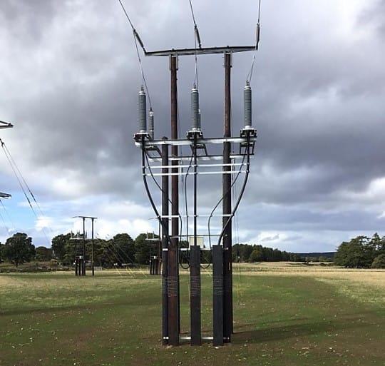
Earthing resistance for pad- or pole-mounted distribution substations
Earthing systems of smaller ground (pad) mounted and pole-mounted distribution transformers usually consist of separate LV and HV earths. This is to avoid the transference of high voltages due to EPR onto the LV MEN system during earth faults on the HV side of the transformer. The separate LV and HV buried earthing systems are also physically separated in the ground by several meters.
There may be three separate resistance measurements required:
- HV earth electrode resistance.
- Overall LV earthing resistance measured near to transformer location.
- Individual LV electrode resistance nearest to transformer.
At a distribution substation the following items in parallel contribute to the measured earth resistance value.
- HV electrode at the substation.
- LV electrode just beyond the substation.
- HV cable screens.
- LV neutral earths beyond substation.
The first three items of the above list should be measured using a clamp-on (contact-less) earth tester device looped around it and the respective neutral earth bar inside the substation cubicle. These individual measurements shall be compared to the value of the overall resistance value taken using the fall of potential method. The clamp-on earth resistance test does not require disconnection/isolation of the electrode under test from the rest of the network. With this type of device, the value of the electrode resistance is measured in series with the rest of the connected electrodes hence the measured value shall only be accurate if the other electrodes in parallel have a low value compared to the electrode under test.
The resistance measured by the clamp-on method tester is the sum of the resistances in the earth loop (i.e. RLV + Rline). Therefore, it is assumed that the resistance of the return path is small enough to be considered negligible against the RLV value such that the total resistance is approximately equal to RLV. If a relatively low resistance return path is not available, then this type of measurement cannot be made accurately.
An alternative to the clamp-on test is the “comparative method” which uses the standard 4 pole test method. In this test the C1 and P1 terminals of the composite tester are connected to an existing low resistance earthing electrode such as an existing substation earth grid or LV earth. The C2 and P2 terminals are then connected to the individual earth electrode under test. Note this test approach requires disconnection of the electrode under test from the apparatus it is protecting therefore the test must only be undertaken when (a) the HV or LV equipment is de-energised; or (b) a suitable alternative electrode system is connected.
Touch and step voltage measurements
Measurements to establish the actual touch and step potentials which a person would be exposed to during a phase-to-ground fault shall be carried out using the current injection technique. With this technique AC current of off-power frequency is injected into the earth through a remote electrode and returned to the earth system under test. The magnitude of injected current represents a scaled-down version of the actual earth fault current.
Scaled-down touch and step potentials are measured using a sensitive frequency tuned voltmeter. Measurements are taken between metal plates in contact with the ground to simulate the human foot and in the case of touch potentials a nearby metallic object 1 m distance away. Step voltages are measured between two metal plates spaced 1 m apart in contact with the ground.
The following step-by-step procedure applies for performing the measurements:
- Measurement locations for touch and step potentials should be marked on a site layout drawing. By referring to the earthing design report and in consultation with the client these locations shall include but not be limited to:
Touch potentials
- At metallic structures, enclosures and objects which can be touched. This includes downpipes and door frames.
- Along metallic substation perimeter fencing.
- Water pipes, taps and hydrants within proximity to the earthing system.
- At telecommunication pits and kiosks within proximity to the earthing system.
Step potentials
- Near the small earthing system electrode or in the case of an enclosed substation immediately outside of the fence where people may approach.
- A set of two shorter leads are connected to the earth system under test. The point of attachment should be cleaned prior to connection.
- Remote current injection earth electrode is set up as per the fall of potential measurement. The minimum separation shall be at least 5 times the diagonal diameter of the earth system under test.
- A continuous current of up to 50 A is injected into the remote earth electrode. The higher the injected current the better the results as they are less susceptible to measurement noise.
- Touch and step voltages are routinely measured at the required locations and recorded.
- Obtained touch and step voltages should be scaled and compared with the permissible touch and step voltage limits as per the applicable standards outlines in the earthing design report.
Safety requirements
The following precautions will minimize the risks associated with current injection testing:
- Persons undertaking the current injection testing must be appropriately qualified, trained and experienced.
- Testing shall not proceed during any lightning activity or planned switching of the plant under test.
- The test equipment operator and the person handling the remote test electrodes must be wearing substantial enclosed footwear and insulating gloves during the period of the tests.
- Operation of and precautions outlined in the test equipment manuals must be understood and adhered to.
- Test equipment should be set up within the confines or near the earthing system under test. This will reduce potential touch voltage hazards. If it is necessary to be situated outside of the area covered by the earthing system, then the equipment should be positioned on top of an insulating mat large enough for the operator also.
- The test connection should connect directly to the earth system under test.
- The test routes should be as clear and straight as possible. Test leads should not be laid in parallel with overhead line conductors (where possible) or at least maintain a minimum separation of 20 m length.
- The injected current flowing between the earthing system under test and remote electrode should avoid intercepting buried metallic objects. This is mainly for providing accurate results.
- Test equipment operator must be continually communicating with person in contact with the remote electrode during the testing.
- No person shall be in contact with the remote electrode during the period of current injection.
- Before connecting or disconnecting a test object the test equipment should be switched off.
- Test equipment must not be connected to or across live apparatus or conductors.
- By the nature of the current injection testing, remote earth potentials are brought into the area of the earthing system under test. During testing all electrical connections shall be treated as hazardous and bare hand contact should always be avoided.
- If any person sees or hears something unusual such as electrical arching during the testing, then the tests must be stopped immediately.
- Safety barriers and/or warning tape should be erected around unaccompanied remote current injection electrodes which are potentially accessible to either uninformed personnel or the public.
- Earthing systems that are connected to live equipment must not be disconnected for testing as there is a risk of a potential difference developing between those connections.
Test Equipment
The required equipment for performing the testing is as follows:
- Four terminals composite earth tester and appropriately rated (voltage and current) leads.
- Earth rod cluster for the remote current injection electrode.
- Long cable with appropriate current-carrying capacity to be run between test equipment and remote injection electrode.
- Single earth rod for measuring voltage.
- Insulating gloves and enclosed footwear.
- Radios or mobile telephones.
- Insulated test mat large enough for test equipment and operator (if required).
- GPS (if required).
Operating principles of the equipment and precautions outlined in the test equipment manuals must be thoroughly understood by the operators and adhered to.
All testing equipment required is to be calibrated such as the current injecting device must be within calibration.
Recommended equipment
- AEMC 6471 Multifunction Earth Tester
- Fluke 1625-2 Geo Earth Ground Tester
- Omicron CPC100 + CP CU1 earth tester (powerful but expensive)