The following tutorial is designed to help users of SafeGrid Earthing Software to learn about and practice the application of powerful operating tools and principles.
Mobile phone repeater station earthing arrangement
The mobile phone repeater station earthing consists of interconnected grid conductors covering the lease area of 9 m by 14.5 m of conductors buried at a depth of 0.5 m. The grid is buried at separation distances of 0.5 m and 1 m from the perimeter fence and the shelter building respectively.
There are three 1 m2 buried plates underneath the concrete pad footing for each leg of the antenna structure.
Rods of 12 m lengths are added as required to reduce the overall earthing resistance.
Figure 1. Sketch of mobile phone repeater station earthing system.
Purpose of the earthing system
The purpose of the earthing system is to provide a low impedance path to the earth from personnel and equipment protection during lightning strikes.
The customer has specified that the total earth grid impedance must not exceed 5 Ω.
Modelling the earth grid in SafeGrid
The earthing grid was drawn using CAD software and imported into SafeGrid as a DXF file. Figure 2 shows the CAD model for earthing arrangement. The model includes the metal plates which were modelled as tightly meshed straight line connected segments.
Figure 2. Model of earth grid drawn in CAD and saved as DXF file for importing into SafeGrid.
Figure 3. DXF CAD file imported into SafeGrid.
Soil resistivity modelling
Soil resistivity measurements were taken in the field using the Wenner Array Method at electrode spacing’s of between 1 m and 8 m due to space limitations. Two sets of measurements were taken in different directions. Note it is good practice to take at least 5 measurements per set.
Figure 4 Wenner field resistivity measurements.
The calculated 2-layer soil model using E-W measurements was as follows (Figure 4):
Top layer resistivity = 6390 Ω-m Depth of top layer = 3.13 m Bottom layer resistivity = 139.3 Ω-m Goodness of fit = 0.928 (very good)
SafeGrid Results – calculated grid resistance
Grid resistance was calculated for the various cases as follows:
Figure 5 Grid resistance was calculated for the various cases.
Plot of grid resistance versus no. of rods
Adding rods is very effective at reducing the grid resistance. This is because the rods are penetrating the relatively low resistivity bottom soil layer.
Figure 6. Plot of grid resistance versus no. of rods.
Conclusion – No. of rods required
In conclusion adding 4 rods to the grid at the corners is enough to reduce the grid resistance to below 5 Ω.
Contact us to request the detailed output results from SafeGrid.
SafeGrid Earthing Software
Easily design safe earthing systems in compliance with Standards.
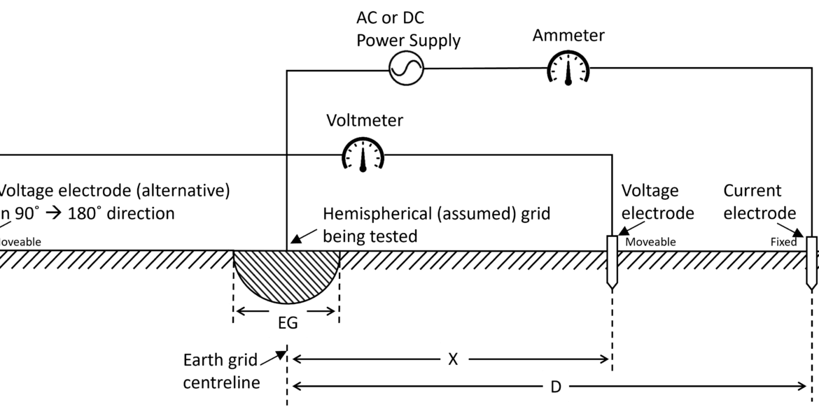
Understand how software simulations enhance grid impedance tests, improving accuracy and efficiency in earthing system design and performance evaluation.
This report explains how to perform accurate earth fault current analysis for substations connected by cable transmission lines. Earth fault currents for simple cable and overhead transmission lines are explained first. Next, two case studies involving hybrid cable transmission lines are presented.
Copper is often preferred for its superior electrical properties, while aluminum and galvanized steel are chosen for cost-effectiveness. Copper-clad steel can offer a balance between cost and performance. This article demonstrates which option is best for different scenarios.
Print this article:
Print
SafeGrid Earthing Software
Easily design safe earthing systems in compliance with Standards.