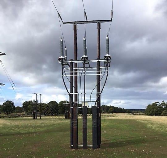
Why use surface material layers in substations?
Inside a substation (often as well as outside the perimeter fence) you will notice a layer of rock or crushed stone, or asphalt. The thickness of this additional surface layer typically ranges from 8-15 cm and there are two main reasons for including it being that:
- It helps to avoid the drying out of topsoil layers during prolonged dry weather periods; and
- It has a very large effect on reducing body currents resulting from touch and step voltages involving a person’s feet.
With regards to the second point, field tests with and without the surface layer have revealed a reduction in body currents in the order of 20 time less. Therefore, covering the surface with a material of high resistivity is very valuable in reducing electric shock currents so it’s common practice. Note it is very important that the integrity of the surface layers is maintained to avoid a compromise in safety.
How to use surface layers for earthing designs
The additional surface layer is included in our calculations for safe touch and step voltage limits using software. When no specific information about the actual surface material resistivity is available the following data may be used [3]:
- Typical crushed rock has a wet resistivity of 3000 Ω.m and a min. thickness of 100 mm.
- Typical asphalt has a wet resistivity of 10,000 Ω.m and a min. thickness of 50 mm. Mitigation of touch or step voltages using asphalt layer should not be performed where touch or step voltages exceed 3 kV and 5 kV respectively due to low flashover withstand of asphalt.
It is up to the designer to confirm wet resistivity value of the actual material being used at site is at least as high as those being assumed in the design model.
Typical surface material resistivities
Typical wet and dry resistivities of materials used for substations are given in Table 1 [1]. Local conditions, size, and type of stone may affect the value of resistivity therefore it is important that the resistivity of rock samples typical of the type being used in a given area be measured.
Table 1—Typical surface material resistivities
| Number | Description of surface material (U.S. state where found) | Resistivity of sample ohm-meter | |
| Dry | Wet | ||
| 1 | Crusher run granite with fines (NC) | 140 × 10 6 | 1300 (ground water, 45 Ω.m) |
| 2 | 1.5 in (0.04 m) crusher run granite (GA) with fines | 4000 | 1200 (rain water, 100 Ω.m) |
| 3 | 0.75 in to 1 in (0.02 m to 0.025 m) granite (CA) with fines | -- | 6513 (10 min after 45 Ω.m water drained) |
| 4 | #4 (1 in to 2 in) (0.025 m to 0.05 m) washed granite (GA) | 1.5 × 10⁶ to 4.5 × 10⁶ | 5000 (rain water, 100 Ω.m |
| 5 | #3 (2 in to 4 in) (0.05 m to 0.1 m) washed granite (GA) | 2.6 × 10⁶ to 3 × 10⁶ | 10 000 (rain water, 100 Ω.m) |
| 6 | Size unknown, washed limestone (MI) | 7 × 10⁶ | 2000 to 3000 (ground water, Ω.m) |
| 7 | Washed granite, similar to 0.75 in (0.02 m) gravel | 2 × 10⁶ | 10 000 |
| 8 | Washed granite, similar to pea gravel | 40 × 106 | 5000 |
| 9 | #57 (0.75 in) (0.02 m) washed granite (NC) | 190 × 106 | 8000 (ground water, 45 Ω.m) |
| 10 | Asphalt | 2 × 10⁶ to 30 × 106 | 10 000 to 6 × 10⁶ |
| 11 | Concrete | 1 × 10⁶ to 1 × 10⁹a | 21 to 100 |
Note that over time the resistivity of surface materials may be reduced through compression and other environmental factors resulting in filling of voids. A surface material exposed to sea spray may have substantially lower resistivity than for that same material installed at inland substations. These factors should be considered during the design phase as well as after the substation is in service.
It is usually recommended that wet resistivity tests be performed for a particular surface layer stone being used for a substation project or by a power utility. The resistivity test of a crushed rock sample is relatively simple (refer to [2]) and does not require a complex laboratory setup.
References:
[1] IEEE Std 80 – IEEE Suide for Safety in AC Substation Grounding
[2] IEEE Std 81:2012 – IEEE Guide for Measuring Earth Resistivity, Ground Impedance, and Earth Surface Potentials of a Grounding System
[3] ENA EG-0:2010 – Power system earthing guide.