Soil electrical parameters at high frequencies
Soil electrical resistivity is one of the most important parameters to consider when designing safe earthing systems especially when analysing behaviour during lightning strikes.
Lightning currents can be represented by around 20,000 distinct frequency components ranging from DC up to several megahertz. Both soil electrical conductivity and permittivity are interrelated according to the Kramers-Kronig relation which goes back to Maxwell’s equations.
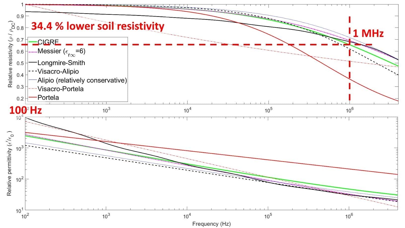
As frequency increases soil effective conductivity increases (resistivity decreases) while effective permittivity decreases, caused by soil ionisation at the high frequencies.
Calculating soil frequency dependency
There are several methods for calculating soil frequency dependency which are explained in CIGRE C4 Technical Brochure 781 [1] where the input to the functions is low frequency DC resistivity. Note that the calculation methods have different frequency range limits for their applicability.
Figure 1 below shows the variation of soil electrical resistivity and relative permittivity (both very important factors for predicting earthing system performance) with increasing frequency based on seven (7) different calculation methods [1]. For example, based on the CIGRE calculation method relative (normalised) soil electrical resistivity is reduced by 34.4 % between 100 Hz and 1 MHz.
Here is an example calculation for a real-world horizontally-stratified soil resistivity model:
A 3-layer soil resistivity model for DC (or power frequency) = [10, 300, 1000] Ω.m
The same soil model at 1 MHz considering soil frequency dependence (CIGRE method was used) = [9.57, 196.7, 441.45] Ω.m
Soil frequency dependence has a favourable effect on earthing systems – grid resistance is reduced with increased frequency.
When to consider soil frequency dependency
Soil frequency dependency is obviously irrelevant at low frequencies and power frequencies under 100 Hz. This is a different consideration at higher frequencies.
The effect of frequency dependency on soil parameters is important to be considered especially when the soil resistivity values are high.
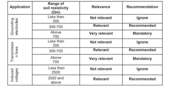
CIGRE C4 TB 781 [1] suggests for buried and transmission line earthing applications that frequency dependency can be ignored for soil resistivities less than 300 Ω.m, recommends it for soil resistivities between 300 and 700 Ω.m, and considers it mandatory for soils above 700 Ω.m.
Figure 2 below summarises the CIGRE recommendations pertaining to earthing system application.
If soil frequency dependency is ignored
During high-frequency faults such as lightning strikes, if constant soil electrical parameters are assumed and soil frequency dependency is ignored the voltage and current responses of an earthing system will be considerably overestimated.
Figure 3 below shows the high-frequency transient voltage (GPR) response for an earthing system with and without considering soil frequency dependency.
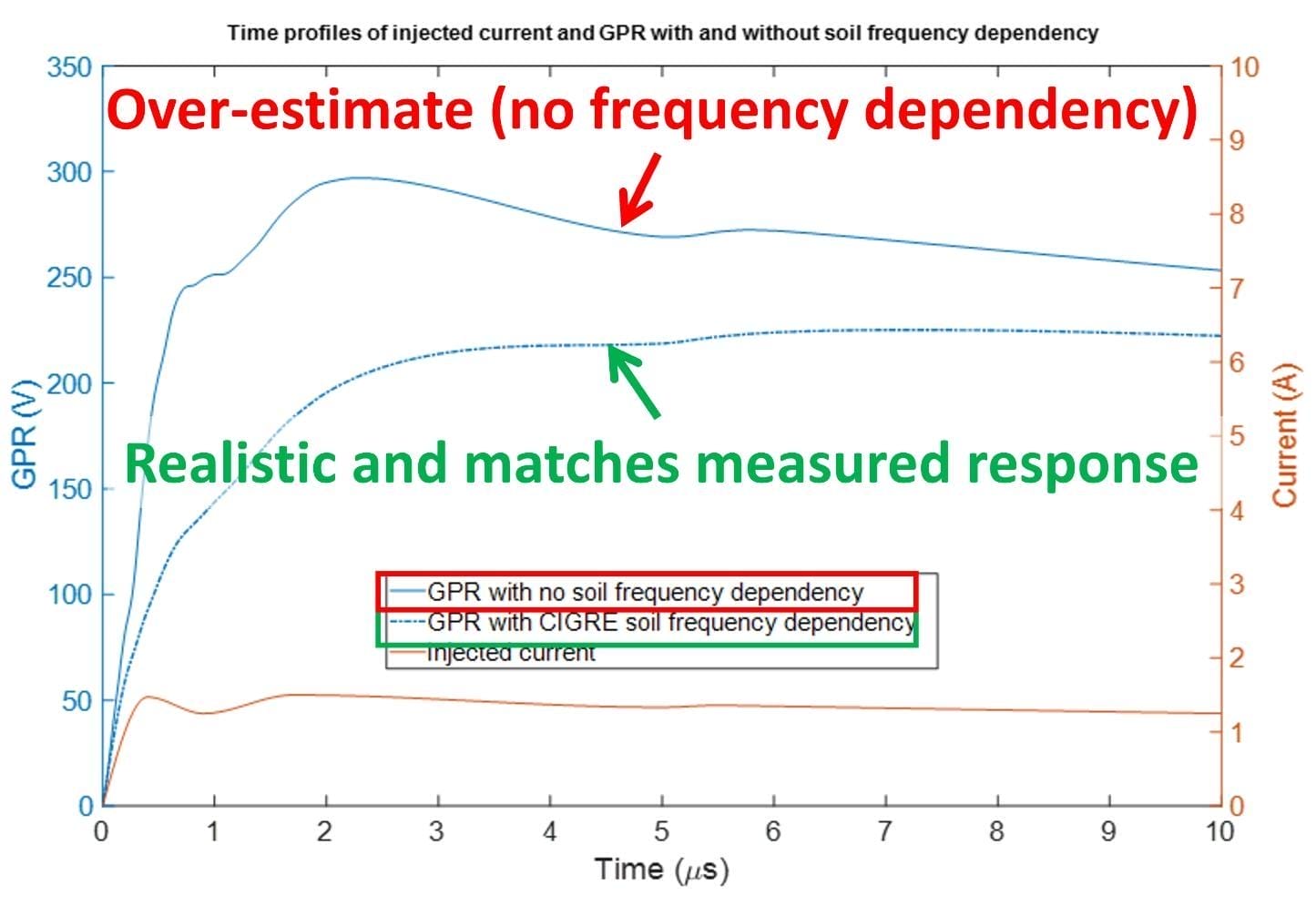
Figure 4 below demonstrates that if soil frequency dependency is ignored for high frequency currents then surface voltages for an earthing system will be completely different compared to if soil frequency dependency is included in the model.

Conclusions
It is important to understand that the behaviour of earthing systems at high frequencies compared with low frequencies is very different. Soil frequency dependency needs to be considered for earthing system modelling and calculations in order to predict performance which closely matches with actual behaviour.
References:
[1] CIGRE Technical Brochure 781 – Impact of soil-parameter frequency dependence on the response of grounding electrodes and on the lightning performance of electrical systems, 2019.


