This article presents the equations for calculating safe touch and step voltage limits (safety criteria) in accordance with the IEEE and IEC Standards and compares their results.
I. INTRODUCTION
A safe earthing system design has two objectives; to provide a means to carry normal and fault current without exceeding equipment limits or adversely affect continuity of service and to reduce the risk of a person in the vicinity of an earthed facility being exposed to a dangerous electric shock.
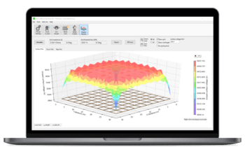
During a typical earth fault condition, the flow of current to earth will produce voltage contours within and around a substation. Figure 1 shows the surface voltage contours during an earth fault for a 132 kV switchyard. SafeGrid Earthing Software was used for performing the modelling.
")
Proper precautions must be taken during the earthing systems design to ensure the maximum touch and step voltages on the earth’s surface during fault conditions do not exceed safe limits which would endanger a person in the area.
After the safe touch and step voltage limits are established the earthing system can then be designed based on the prospective fault current and associated protection clearing time.
This paper presents the equations for calculating safe touch and step voltage limits in accordance with the latest international Standards at power frequencies (50Hz/60Hz) as well as examining the differences and the results.
A note about safe limits for high frequencies: There are currently no safe limit equations or Standards which provide touch and step voltage limits for lightning currents. It has been proposed by recent literature that a touch and step voltage limit of 2kV and 25kV respectively could be used for lightning impulse current waveforms with a 10/350µs shape. Refer to reference [ref. 9].
II. SAFETY STANDARDS
The effect of electric current on the human body depends on several factors including the magnitude and duration of the fault current as well as frequency. Derivation of minimum safety criteria is based on fundamental knowledge about these effects and numerous scientific investigations have been undertaken to determine the safe limits.
Standards have been developed around the science, which provide permissible levels of body current to avoid the deaths of people exposed to electric shocks.
The two main safety standards are IEEE Std 80-2013 [1] and IEC 60479-1:2010 [2]. The British standard BS 50522:2010 and the European standard EN 50522:2010 are derived from the IEC 60479-2010.
III. MATHEMATICAL FORMULATION
A. IEEE Std. 80-2013
• Tolerable body current limits
Fibrillation current is assumed to be a function of a person’s body weight. This idea comes from studies undertaken by Dalziel [5]. Thus, the formulae for allowable body current which can be survived by 99.5% of persons are given for two weights (50 kg and 70 kg):

where tf is the fault clearing time in seconds (0.03 to 3 s).
• Body Impedance
A constant body impedance of 1000 Ω is considered. This is excluding the resistance of the foot. The human foot is represented as a conducting metallic disc with a radius of 0.08 m and the contact resistance of shoes, socks, etc., is neglected. The foot resistance is calculated for the touch and step voltage is given by:

where ρs is the resistivity of the surface layer
Cs is the scaling factor due to the presence of the protective surface layer.
• Effect of Surface Layer Material
The Cs factor in the computation of foot resistances is to account for the effect of a surface layer in a substation (usually a high resistivity crushed rock layer). The computation of Cs is based on a rigorous series expression, with each term being a surface integral. Spreading a thin (usually 8-15 cm thick crushed rock) layer of high resistivity material over the surface within a substations increases allowable touch and step potentials. This is because a high resistivity surface layer provides additional series resistance with the body, thereby reducing the body current during a fault situation. The resistivity of the surface layer should be at least 5 times higher than the top soil layer resistivity to have any great benefit [6]. These effects of the surface layer on allowable touch and step potentials are accounted for with the inclusion of a scaling term (Cs) into the foot resistance (Rf) calculation. In the absence of a surface layer ρ = ρs.
• Additional Resistances
The consideration of additional resistances such as shoes, gloves etc. are not allowed by this standard.
• Touch Voltage
The potential difference between the ground potential rise (GPR) of a ground grid or system and the surface potential at the point where a person could be standing while at the same time having a hand in contact with a grounded structure is known as the touch voltage. The touch voltage is given by
• Step Voltage
The difference in surface potential that could be experienced by a person bridging 1 m with the feet without contacting any grounded object. The step voltage is given by
B. IEC 60479-1:2010
• Tolerable body current limits
The fibrillation current used in this standard is a function of the duration of current flow. The current threshold for ventricular fibrillation for a current path hand to feet is given in Fig. 2.
")
The zones of interest are AC-4 for the boundaries c1, c2 and c3. There is a dramatic reduction shown in tolerable currents (turning point in the graph) at around 400 ms. This is due to the likely interference of the fault current with the T-phase (occurs at around 400 ms) of the heart pulse which is more likely to cause fibrillation of the heart.
• Body Impedance
A body impedance model is given with touch voltage thresholds related to the touch current thresholds by the body impedance according to Ohm’s law. The hand to hand impedances are given for the 5th, 50th and 95th percentiles of the population for both wet and dry conditions. The body impedance values corresponding to the 5th percentile (representing greater than 95% of the population) are lower and the most conservative from a safety perspective since they would result in higher current through the body. The hand to foot body impedance is 10 – 30% less than the hand to hand body impedance. This is different from IEEE Std. 80 which uses a fixed value of 1000 Ω.
IEC 60479 defines other body current paths which may be considered. When other body current paths are considered the hand to foot impedance is converted into the corresponding current path impedance using the body factor as shown in Fig. 3.
")

• Foot and Additional Resistances
The foot resistance is calculated as per IEEE Std. 80 or a custom foot resistance may be used. Additional resistances such as shoe, glove etc. are allowed in this standard.
• Prospective Voltages
While IEEE Std. 80 provides a direct method for establishing safety criteria (allowable touch and step potentials) for substations, IEC 60479 does not. The necessary method is explained in the following steps:
1. For a given fault clearing time and assumed probability of ventricular fibrillation determine the value of permissible body current from Fig. 1
2. For the permissible body current level determine the corresponding body resistance using the Tables.
3. Compute the foot resistance in accordance with IEEE Std 80-2013.
4. Compute permissible touch and step potentials.

C. CENELEC EN 50522:2010
This standard is very similar to the IEC 60479 except for the following differences.
• Body Impedance
The body resistance is calculated based on Table 1 of IEC 60479-1:2010 (50/60 Hz, hand-to-hand total body impedance vs voltage, in dry conditions with large contact area), 50% population percentile rank.
• Tolerable Body Current Limits
The threshold current is determined from the 50% probability of fibrillation C2 curve (Shock Duration vs Body Current) in Figure 20 of IEC 60479-1:2010.
D. BS 50522:2010
This standard is also very similar to the IEC 60479 except for the following differences.
• Body Impedance
The body resistance is calculated based on Table 1 of IEC 60479-1:2010 (50/60 Hz, hand-to-hand total body impedance vs voltage, in dry conditions with large contact area), 5% population percentile rank.
• Tolerable Body Current Limits
The threshold current is determined from the 50% probability of fibrillation C2 curve (Shock Duration vs Body Current) in Figure 20 of IEC 60479-1:2010.
IV. SIMULATION RESULTS
The following simulation of touch and step voltages using the IEEE Std. 80 and the IEC 60479-1 is carried out under the following conditions:
• Surface layer not present.
• No additional resistances are considered.
• The foot resistance is computed as per IEEE Std. 80.
A. IEC 60479-1:2010
The calculations of touch and step voltages as per the IEC standard uses the three probabilities of fibrillation, c1, c2 and c3. The body impedance not exceeded by 50% of the population is considered. The surface area of contact is large and dry contact conditions are used. The heart current factor for the touch and step voltages are taken as 1 (conservatively). The body factor for the touch voltage is 74.25% and that for the step potential is 1.015%. Fig. 4 and Fig. 5 shows the allowable touch and step voltages for varying fault clearing times from 0.01s to 1 s.


B. IEEE Std. 80
The touch and step voltage calculations for IEEE Std. 80 are carried out for body weights of 50 kg and 70 kg. The standard body impedance of 1000 Ω is used. Fig. 6 and Fig. 7 shows the allowable touch and step voltages for varying fault clearing times from 0.03 s to 1 s.


V. CONCLUSION
The calculation of safety criteria prescribed in IEC 60479 is not straight-forward whereas for IEEE Std. 80 it is. IEC 60479 does not provide a method for calculating foot resistance. IEEE Std. 80 assumes a fixed body resistance value of 1000 Ω and this simplification may compromise safety. IEEE Std. 80 defines safety criteria for a given body weight whereas IEC 60479 states that the body impedance is not greatly influenced by body mass.
IEC 60479 safety limits are based on recent knowledge surrounding interference of the fault current with the T-phase (occurs at around 400 ms) of the heart pulse which is more likely to cause fibrillation of the heart. IEC 60479 allows the calculation of voltages through other body paths using the heart current factor and the body factor.
The safety criteria for IEEE Std. 80-2013 and IEC 60479-1:2010 have been compared and the differences have been quantified. In general, the IEC Standard allows for higher safe limits for fault durations shorter than 400 ms compared with the IEEE Standard.
Note on Decrement factor
The decrement factor is an adjustment factor used in conjunction with the symmetrical ground fault current parameter in earthing calculations. It determines the rms equivalent of the asymmetrical current wave for a given fault duration, accounting for the effect of initial dc offset and its attenuation during the fault [1].
IEEE Std. 80 defines the effective asymmetrical fault current as the multiplication of the calculated decrement factor and the RMS symmetrical fault current.
We believe best practice is to apply the decrement factor to the fault current which leads to a real increase in the RMS AC current at power system frequency along with a real increase in earthing safety-related voltages. We do not agree with applying decrement factor to the safety criteria allowable voltage limits as a reduction factor for the reasons given by [9].
REFERENCES
[1] IEEE Std 80.-2013. IEEE Guide for Safety in AC Substation Grounding, The Institute of Electrical and Electronics Engineers, Inc.
[2] IEC 60479-1:2010. Effects of current on human beings and livestock – Part 1: General aspects.
[3] CENELEC EN 50522:2010 Earthing of power installations exceeding 1 kV a.c.
[4] BS EN 50522:2010 Earthing of power installations exceeding 1 kV a.c.
[5] Dalziel, C. F. (1946). “Dangerous electric currents.” AIEE Transactions on Power Apparatur and Systems 62: 579-585.
[6] Dawalibi, F. (1982). Transmission Line Grounding. EL-2699, Research Project 1494-1. Montreal, Quebec, Canada, Safe Engineering Services Ltd. 1.
[7] Dawalibi, F. (2003). “Effects of the changes in IEEE Std 80 on the design and analysis of power system grounding.”
[8] Thapar, B., V. Gerez, et al. (1994). “Reduction factor for the ground resistance of the foot in substation yards.” IEEE Transactions on Power Delivery 9(1): 360-368.
[9] Tocher, W. J. V., Pawlik, B., Woodhouse, D. J., & Shaw, C. (2016, September). On decrement factor how and why X/R correction is used and abused. In 2016 Down to Earth Conference (DTEC) (pp. 1-7). IEEE.
[9] Suchanek. S. et al, Simulation of earth termination systems for lightning protection systems regarding step voltages, 2011.