Firstly let’s start with the following definition. Touch voltage is the potential difference between the grid potential rise (GPR) of an earthing grid or system and the surface potential at the point where a person could be standing while at the same time having a hand in contact with a grounded structure.
Figure 1 below depicts the touch voltage scenario where the fault current If is being discharged into the earthing system of the substation. Point H is at the same potential as the earth grid into which the fault current flows, and point F is the point on the ground surface in contact with the person’s two feet. The body current Ib flows from H to F.
Figure 1. Touch voltage scenario (Ref. 1).
Reach touch voltages are different to touch voltages.
Reach touch voltage is automatically set to zero when the distance between the voltage point on the ground surface (representing the location of a person’s feet) and the nearest grid conductor which is touched exceeds a user-specified reach distance (often reach distance is 1.5 meters). Reach touch is useful when there is a certainty that earth conductors are farther away than a person could touch, which otherwise leads to reporting of touch voltages that are inflated.
Calculating reach touch voltages - Example
Below are the calculated touch voltage results for a 110 kV substation earthing system. The calculations were performed using ELEK SafeGrid Earthing Software. Figure 2 shows the grid model consisting of the substation and building earthing system, which are bonded together.
Figure 2. Model of substation and building earthing systems.
Figure 3 below provides a regular touch voltage plot where touch voltages are shown for all of the areas, even where it would not be possible for a person to be in contact with the earthing system. Notice that the maximum touch voltage of 270 V (grossly inflated) is at the plot image’s North East and South West far corners.
Figure 3. Touch voltage plot for all locations.
Figure 4, on the other hand, is a reach touch voltage plot where touch voltages on the ground are shown if they are within reach distance. The maximum touch voltage, in this case, is 118 V.
Figure 4. Reach touch voltages plot (touch voltages within 1.5 m reach distance).
Reach touch voltages for renewable projects
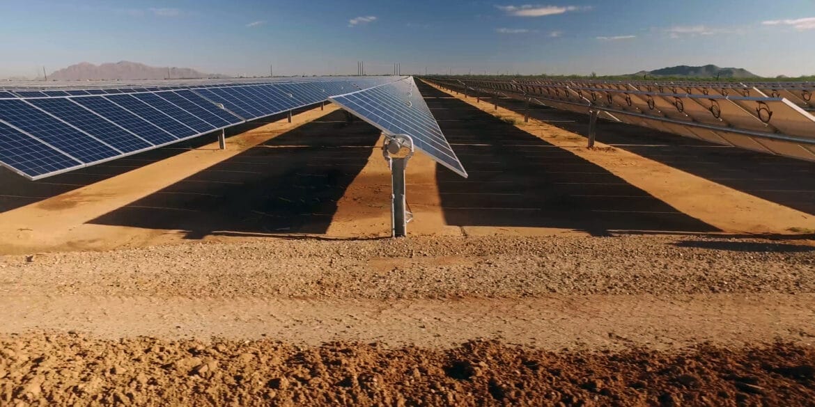
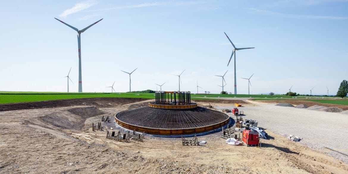
Due to the large areas covered by solar PV and wind farms and their associated earthing grids, the use of the reach touch concept and practical application with the software modelling can be useful.
This is because with the reach touch voltage approach the grid reference voltage used is not the Grid Potential Rise (the maximum voltage of the grid which may be far away from where the touch voltage is being calculated) but it uses the voltage of the nearest grid conductor as the reference.
For example, if you are examining the touch voltages at the PV panel structures at the far end of the solar plant and the earth fault scenario is a fault at the main substation then if you use GPR at the substation for the touch voltage reference then touch voltages may be grossly overestimated. The same applies for wind farms when considering the touch voltages at the individual wind turbines for an earth fault at the main substation (most likely they are a very far distance apart).
Key takeaways:
The following are the key takeaways for reach touch voltages:
Reach touch is useful when there is a certainty that earth conductors are farther away than a person could touch, which otherwise leads to reporting of touch voltages that are inflated.
It is advisable that designers should first attempt to make an earthing system safe using standard touch voltages; if that is not possible, they can use reach touch voltages to help.
Care must be taken that other above-ground conductors do not transfer the grid voltage to where the person is standing away from the grid.
The use of reach touch voltages also does not account for future minor changes, such as temporary fencing that is erected and earthed or new CCTV towers that can extend into areas away from the modelled earthing system conductors. These minor works do not usually trigger thoughts of whether the earthing system should be modified accordingly. Therefore, it is best to design the earthing to provide safety across the whole fenced area.
Further demonstration of touch voltage overestimation
This simple example shows that for calculating touch voltages the voltage of the conductor nearest to the touch location should be used for the calculations.
The model consists of two 30 metre square mesh earth grids separated by 300 metres and bonded together with a single insulated bonding conductor (the same concept being demonstrated holds if the bonding conductor were bare also).
A fault is applied at Grid 1 and the voltage of the conductors are 436.2 V (GPR) and 272.8 V at Grid 1 and Grid 2 (a difference of 163.4 V). Let’s consider what would be the touch voltage a person would experience if located at Grid 2. If the grid conductor voltage at Grid 1 (which is GPR) is used as a reference the touch voltage is overestimated to be 298.4 V. On the other hand, if the reference used was the voltage of the nearest (within reach) conductor of Grid 2 then the actual touch voltage would be 83.8 V which in this case is much lower.
Figure 5. Calculation of touch voltages for two separated earth grids bonded together - Plan (2D) view.
Below are line plots of touch voltages for the same two separated grids.
Figure 6. Calculation of touch voltages for two separated earth grids bonded together - Line plots.
References
[1] IEEE Std 80-2013, IEEE Guide for Safety in AC Substation Grounding.
SafeGrid Earthing Software
Easily design safe earthing systems in compliance with Standards.
Understand how software simulations enhance grid impedance tests, improving accuracy and efficiency in earthing system design and performance evaluation.
This report explains how to perform accurate earth fault current analysis for substations connected by cable transmission lines. Earth fault currents for simple cable and overhead transmission lines are explained first. Next, two case studies involving hybrid cable transmission lines are presented.
Copper is often preferred for its superior electrical properties, while aluminum and galvanized steel are chosen for cost-effectiveness. Copper-clad steel can offer a balance between cost and performance. This article demonstrates which option is best for different scenarios.
The technical guide explains the electrical systems, local WTG and combined earthing system design, touch and step voltage hazards, soil electrical resistivity measurements, earth fault currents, earthing system software modelling, and validation testing of earthing for wind farms.
.")


.")
 view.")