Tutorial on how to import and model custom buried earthing systems using SafeGrid Earthing Software.
Modelling earth grids using CAD
SafeGrid Earthing Software can import grids which were drawn in 2D or 3D using a CAD program which can export files in the DXF file format.
Advantages of importing grids
The advantages of importing grids from CAD include:
1. Earthing design drawings which have been developed in CAD can be imported without re-drawing. This saves time and also ensures the model representation of the grid accurate.
2. Complicated and custom grids can be analysed.
3. Conductor arrangements in 3 dimensions (3D) – X, Y, Z co-ordinates system can be modelled.
Draw the grid based on the design drawings using CAD software ensuring that the drawing rules mentioned in the tutorial (link above) are followed.
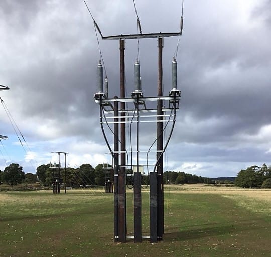
Below is an example earthing arrangement for an earthing turbine which was modelled. The design is based on an earthing practice adopted in the U.K. which uses buried metal plates connected by radial (counterpoise) conductors.
The following design was selected due to its novelty and challenges in modelling. This arrangement will not be the most economical design for all soil types.
Figure 2. Engineering drawing wind turbine earthing grid in 3D.
The model of the wind turbine earthing arrangement includes:
Reinforcement meshes which is contained within the concrete foundation of the wind turbine. The mesh is connected to the earth grid and thus included in the earthing model to reduce grid impedance as well as step and touch potentials.
Metal plates buried at the ends of 12 metre long counterpoise conductors. These plates were represented as tightly meshed straight line connected segments and were buried at 2 + metres (Z = 2 m).
Figure 3. Earthing grid for wind turbine drawing in 3D CAD.
Importing 3D DXF File into SafeGrid
Under Build Grid go to Load DXF File.
Lines to include can be either All Lines or Lines in Layer. Specify the Layer Name(s) for the latter.
Select Depth of Lines in DXF File. This ensures SafeGrid will read also read the Z co-ordinates for the Line start and end points.
Figure 4. Depth of Lines in DXF File.
Setting the Fault Location Segment no.
Figure 5. Imported 3D DXF File model of wind turbine earthing into SafeGrid.
SafeGrid’s advanced algorithms include modelling of the conductor series impedances. Therefore it is important to specify the location (conductor segment) of the grid where the fault current is applied during the simulations. This affects the dissipation of fault current and also the distribution of surface, step and voltages.
For example, the surface voltage profile is very different when the fault current is applied at the end of one of the long counterpoise (radial) conductors compared to when it is applied at the centre of the reinforcement mesh.
Set Fault Location Segment No. equal to 200.
Figure 6. Setting the Fault Location Segment no.
Setting surface voltage plot locations
Go to Safety Criteria module.
Under Plot Surface Voltages select Over area.
Set Maximum spacing between points (m) equal to 0.2 m.
Figure 7. Setting surface voltage plot locations under Safety Criteria.
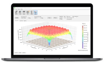
SafeGrid Results
SafeGrid outputs detailed results to a comprehensive PDF report.
Note that numerous of the application and site specific data has not been set, calculated or discussed. This includes grid energisation (fault current) level, soil resistivity model, grid conductor size or safety criteria standards and limits.
For this example the following basic data was used.
Soil resistivity:
Top layer resistivity = 100 Ohm.m Top layer depth = 5 metres Bottom layer resistivity = 30 Ohm.m
Frequency = 50 Hz Phase-to-earth fault current = 500 A
Conductor sizing: Copper (annealed) conductor 70 mm2. Based on ultimate fault current of 12 kA for 1 second.
SafeGrid Earthing Software
Easily design safe earthing systems in compliance with Standards.
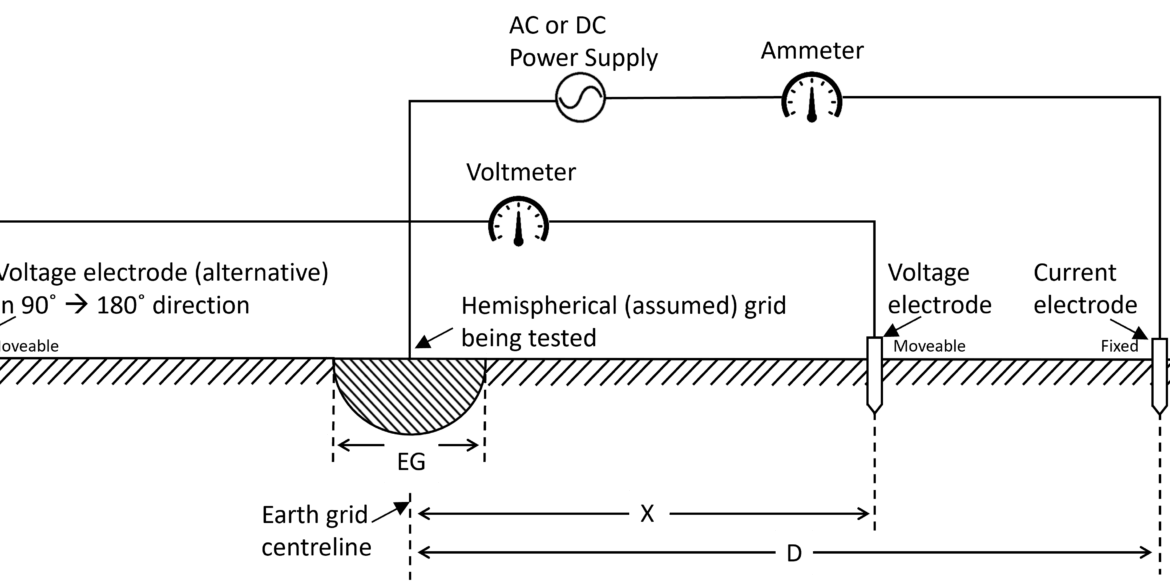
Understand how software simulations enhance grid impedance tests, improving accuracy and efficiency in earthing system design and performance evaluation.
This report explains how to perform accurate earth fault current analysis for substations connected by cable transmission lines. Earth fault currents for simple cable and overhead transmission lines are explained first. Next, two case studies involving hybrid cable transmission lines are presented.
Copper is often preferred for its superior electrical properties, while aluminum and galvanized steel are chosen for cost-effectiveness. Copper-clad steel can offer a balance between cost and performance. This article demonstrates which option is best for different scenarios.
Print this article:
Print
SafeGrid Earthing Software
Easily design safe earthing systems in compliance with Standards.