Table of Contents
Using bentonite to reduce resistance
Sometimes it is not possible to achieve the desired reduction in ground resistance by adding more grid conductors or ground rods. An alternate solution is to effectively increase the diameter of the electrode by modifying the soil surrounding. It has been shown that the inner shell of soil closest to the electrode has the greatest affect on the resistance as measured to remote earth [1]. This phenomenon can be taken advantage of by surrounding the electrode or rod with a material like bentonite, a natural clay containing the mineral montmorillonite, to lower the resistance.
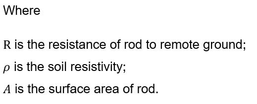
According to the results of reference [2], rods that are surrounded with bentonite show a significant lowering of resistance to remote ground as compared with direct driven rods. The reduction in resistance is a direct result of increasing the effective surface area of the ground rod. As you increase the surface area in contact with a given resistivity soil, the resistance of the rod to remote ground will drop according to the relationship:

How to model rods surrounded with bentonite
Bentonite clay has a very low, almost negligible resistivity, so by surrounding the rod, for example, within a 152mm (6 in.) cylinder of bentonite, we have effectively installed a 152mm (6 in.) ground rod and we can expect the resistance of the rod to drop.
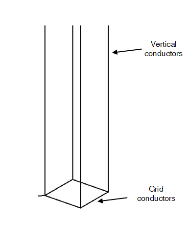
A test grid with a 20 m long rod is investigated to find out how to model the rod surrounded by bentonite. To represent a rod surrounded with bentonite in software we include several vertical conductors of which the circumscribed circle has the area of the bentonite.
Figure 1 shows that the rod surrounded with bentonite is modelled as four and twelve normal size vertical conductors respectively.
Figure 1 – Two models of a rod surrounded by bentonite
The grid conductor area is assumed as 70 mm2 and the cross-section area of the bentonite is assumed as 10000 mm2. Table 1 shows the grid impedance of different cases.
Table 1 – Grid impedance of different cases
| No. | Cases | Grid impedance (Ω) | Variation compared with 1st case |
|---|---|---|---|
| 1 | A 10000 mm2 rod | 4.213 | N/A |
| 2 | A 70 mm2 rod | 5.809 | + 37.88% |
| 3 | Four 70 mm2 vertical conductors used to model rod surrounded by bentonite | 4.365 | + 3.61% |
| 4 | Twelve 70 mm2 vertical conductors used to model rod surrounded by bentonite | 4.290 | + 1.83% |
The rod surrounded by bentonite can significantly reduce the grid impedance according to case 1 and 2. In SafeGrid, several small cross-section area rods cane be used to model the rod with bentonite. The results of case 3 and 4 validate the effectiveness of this method. Their grid impedances are close to that of a 10000 mm2 rod. Based on the comparison between 3rd and 4th cases, the grid impedance becomes less and closer to the ideal situation as the number of vertical conductors increases.
Conclusion
The use of moist bentonite clay can improve the performance of earthing rods effectively by reducing their effective resistance. Grid impedance and grid potential rise (GPR) will thereby decrease significantly.
In SafeGrid Earthing Software, vertical conductors located at the vertices of an equilateral polygon which has the same area of bentonite can be applied to model the rod surrounded by bentonite. As the number of these conductors increases, the calculated resistance results for the rod approach that for an actual rod surrounded with bentonite.
References
[1] “IEEE Guide for Safety in AC Substation Grounding,” IEEE Std 80-2013 (Revision of IEEE Std 80-2000/ Incorporates IEEE Std 80-2013/Cor 1-2015), pp. 1-226, 2015, doi: 10.1109/IEEESTD.2015.7109078.
[2] W. R. Jones, “Bentonite Rods Assure Ground Rod Installation In Problem Soils,” IEEE Transactions on Power Apparatus and Systems, vol. PAS-99, no. 4, pp. 1343-1346, 1980, doi: 10.1109/TPAS.1980.319556.
