0

Your Cart

0
Subtotal: AUD0
No products in the cart.

How to model earthing surrounded with bentonite

Model earthing conductors and enhancement materials as an equivalent conductor

Materials used to enhance earthing systems

If it is not possible to achieve the desired earth grid resistance by adding more grid conductors or ground rods, an alternate solution is to effectively increase the diameter of the electrode by modifying the soil surrounding the grid conductors.

A number of enhancement method and materials may be used to surround the earthing system grid conductors which in turn will improve their performance. These include the following:

1. Use of sodium chloride, magnesium, and copper sulphates, or calcium chloride, to increase the conductivity of the soil immediately surrounding an electrode. Note that there is a risk of leaching into surrounding areas, which may not be allowed and also that the salts must be renewed periodically.

2. Use of bentonite, a natural clay containing the mineral montmorillionite, which was formed by volcanic action years ago. It is noncorrosive, stable, and has a resistivity of 2.5 Ω·m at 300% moisture. The hygroscopic nature of bentonite will take advantage of the available water to maintain its as installed condition. If exposed to direct sunlight, it tends to seal itself off, preventing the drying process from penetrating deeper. It may not function well in a very dry environment, because it may shrink away from the electrode, increasing the electrode resistance.

3. Chemical-type electrodes consist of a copper tube filled with a salt. Holes in the tube allow moisture to enter, dissolve the salts, and allow the salt solution to leach into the ground. These electrodes are installed in an augured hole and typically back-filled with soil treatment.

d) Ground enhancement materials, some with a resistivity of less than 0.12 Ω·m (about 5% of the resistivity of bentonite), are typically placed around the rod in an augured hole or around grounding conductors in a trench, in either a dry form or premixed in a slurry. Some of these enhancement materials are permanent and will not leach any chemicals into the ground. Other available ground enhancement materials are mixed with local soil in varying amounts and will slowly leach into the surrounding soil, lowering the earth resistivity.

How to model the earthing enhancement materials

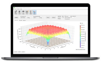
Earthing system modelling software is used to predict the electrical performance of buried earthing systems and these enhancements can be included in the computer models. 

To include the enhancement material treat the actual buried conductor and surrounding substance combined as a buried conductor of an equivalent (calculated) radius.

Figure 1 Earthing grid parameters with conductor surrounded by an additional substance.
Figure 2 Earthing grid parameters with conductor surrounded by an additional substance.

Approximate analytical equation

Formulae - How to model earthing surrounded with bentonite


Where

Where Formulae - How to model earthing surrounded with bentonite

Example

Example Formulae - How to model earthing surrounded with bentonite
Formulae2 - How to model earthing surrounded with bentonite

SafeGrid Earthing Software

Easily design safe earthing systems in compliance with Standards.

Related Articles:

Experienced electrical engineers created this reference list of standards for power systems earthing/grounding for substations, renewable energy, etc.
Understand how software simulations enhance grid impedance tests, improving accuracy and efficiency in earthing system design and performance evaluation.
This report explains how to perform accurate earth fault current analysis for substations connected by cable transmission lines. Earth fault currents for simple cable and overhead transmission lines are explained first. Next, two case studies involving hybrid cable transmission lines are presented.
Copper is often preferred for its superior electrical properties, while aluminum and galvanized steel are chosen for cost-effectiveness. Copper-clad steel can offer a balance between cost and performance. This article demonstrates which option is best for different scenarios.
The technical guide explains the electrical systems, local WTG and combined earthing system design, touch and step voltage hazards, soil electrical resistivity measurements, earth fault currents, earthing system software modelling, and validation testing of earthing for wind farms.
There are two reasons, according to the standards, why crushed rock or gravel is laid in substations, as explained in this article.

Print this article:

Print

SafeGrid Earthing Software

An electrical device with software and a graph on its screen.

Easily design safe earthing systems in compliance with Standards.

As used by:

SafeGrid Earthing Clients