Lightning protection systems are designed to protect structures and prevent or minimize damage or injury that may be caused due to a lightning strike. These systems comprise air terminals, down conductors, equipotential bonding and buried earthing conductors and they should safely discharge the lightning currents into the general body of the earth.
A well-known Standard providing practical guidance on lightning protection system design is IEC62305 [2]. The lightning currents generated during a strike occur rapidly and are of extremely high magnitude.
This paper explains the effects of a direct lightning strike to an air terminal on top of a building structure which is connected to a buried earthing system.
Example building lightning protection and earthing system
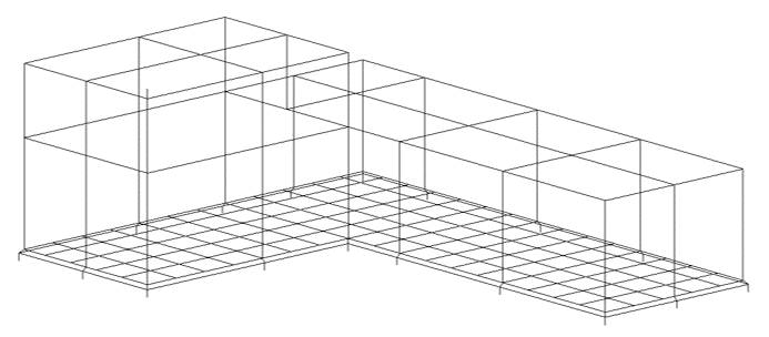
In an example a building earthing system comprising an interconnected above ground down conductor network and buried earthing grid with driven rods was modelled.
The overall building height is 30 m. There are several 2.5 m tall air terminals designed to intercept the lightning current installed at the corners of the roof of the building.
The rebar installed inside the concrete slab of the building foundation is modelled as a mesh which is connected to the earthing system. A grading ring buried at 0.5 m surrounds the perimeter of the building with several 2-metre-long earth rods installed. The buried earthing system is installed in multilayer soil where the resistivity and permittivity are both frequency dependent.
A worst-case (first positive impulse 10/350 µs) lightning current was applied to a single air terminal as simulating a direct lightning strike.
Simulation results – Direct lightning strike to the building
When lightning strikes an air terminal of a lightning protection system on top of a building the high-frequency currents flow downwards along the interconnected conductors.
The currents which flow along the conductors are called longitudinal currents and these exist in both the above- and below ground conductors. As current flows along the conductors in the network a voltage rise occurs which is maximum at the air terminal location and is attenuated along the conductors since like any electrical conductor, the conductors exhibit impedance to the flow of electrical current. Once the currents reach the buried earthing they are leaked into the ground, referred to as leakage currents, which depends on the series and mutual impedances between the conductors in the soil.
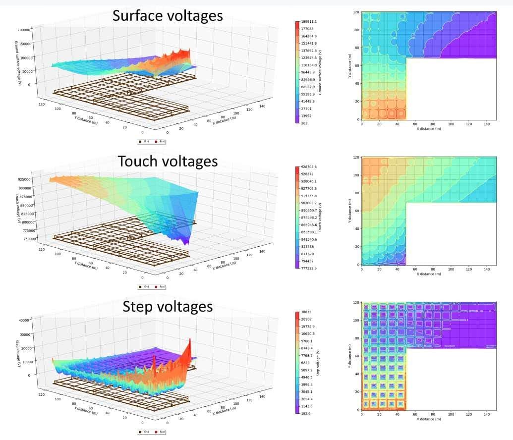
The high-frequency currents as they are dissipated create a potential rise in the surrounding soil resulting in surface voltages, as well as touch or step voltages hazards.
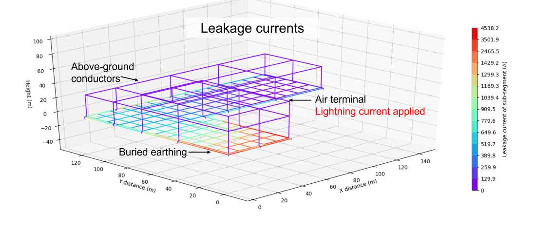
Leakage currents plot
The image shows that (as expected) none of the lightning current leaks from any of the above ground earthing. On the other hand, all the current is leaked into the soil by the below ground earthing. Higher levels of current are leaked by the buried conductors which are near to the air terminal and the perimeter conductors compared with the inner conductors in the mesh. Note that when low frequency faults occur the spread of leakage currents is higher and more evenly distributed amongst the buried earthing conductors.
Longitudinal currents plot
The image shows maximum longitudinal currents exist nearest the faulted conductor (where the maximum current is injected) and that this current is then split between other conductors which are interconnected as it ultimately flows towards the ground.

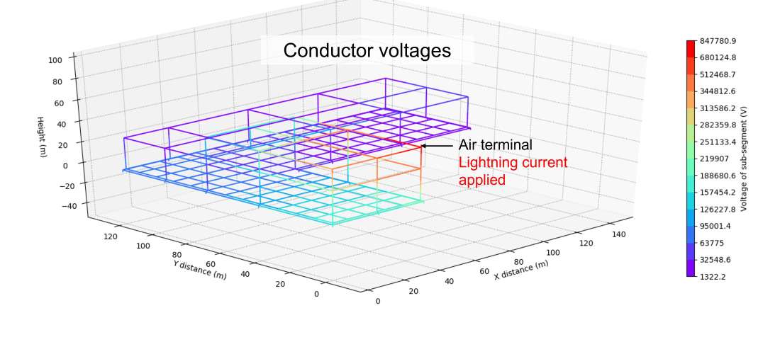
Conductor voltages plot
The image shows the voltages of the conductors which are again highest near to the fault conductor and lowest on conductors farther away from the faulted conductor. In the case of high-frequency lightning currents not only is the maximum conductor voltage very high but the difference between the maximum and minimum conductor voltages is also great. However, this is very different compared with low-frequency faults where the highest and the lowest voltages are quite close especially for a meshed network of conductors.
Surface, touch, and step voltage plots
The image shows the voltages that occur on the ground level because of the lightning current being dissipated into the soil.
Conclusion
When lightning strikes occur on an air terminal installed on top of a building the distribution of currents and the resultant voltages on the lightning protection and the earthing system are complicated to predict.
It was important to include the above ground and buried conductors in the model.
The results presented by this study show in general what to expect and explains why. However, each individual case (installation) must be modelled specifically.
References:
[1] Safe Grid Earthing Software, Version 6.0.
[2] IEC 62305 Protection against lightning.


