Table of Contents
Introduction
Meeting a specified earth-grid resistance is sometimes required in electrical infrastructure projects. In practice, many grounding systems fail to achieve the target value during design verification or on-site testing. Earth rods are added, conductor sizes are increased, and mesh density is changed, but often with little reduction of the measured resistance.
This article explains the factors that reduce earth grid resistance, based on calculated results and grounding system behaviour.
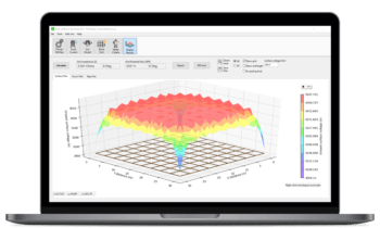
The calculations and modelling were performed using ELEK SafeGrid Earthing Software.
What Controls Earth Grid Resistance
Earth grid resistance is governed primarily by:
- The physical size of the grounding grid
- The resistivity of soil layers, including variation with depth
- The effective interaction between the grid and the surrounding soil
- Whether the grid is bonded to other grounding systems
Copper quantity alone is not a reliable predictor of resistance reduction.
Video Overview: This video explains the relative effectiveness of common earth grid design modifications and identifies which changes materially reduce earth grid resistance based on grounding system behaviour and calculated results.
Presentation Slides
Download the full PDF slide deck of this article for your reference.
Increasing Grid Area
Relative effectiveness: Very high
Increasing the physical area of a grounding grid is one of the most effective ways to reduce earth grid resistance.
A larger grid engages a greater volume of soil, thereby directly reducing the resistance between the grid and the earth. This effect is consistently larger than changes achieved through conductor sizing or mesh densification.
Design limitations and considerations:
- Often constrained by site boundaries and existing infrastructure
- It may be impractical for brownfield substations or space-constrained installations
Adding Earth Rods
Relative effectiveness: High (condition-dependent)
Earth rods can reduce earth grid resistance when they penetrate soil layers with lower resistivity than the surface layer.
Where deeper soil resistivity is favourable, rods can provide meaningful reductions in resistance. Where it is not, additional rods deliver little benefit.
Design limitations and considerations:
- Ineffective if the deeper soil resistivity is higher than the surface soil resistivity
- Performance is sensitive to rod spacing due to proximity effects
- Can lead to unnecessary costs if soil layering is not assessed
Bonding to Adjacent Grounding Systems
Relative effectiveness: Very high
Bonding a grounding grid to nearby grounding systems is often one of the most effective methods of reducing earth grid resistance.
Bonding increases the effective grid area and allows a larger soil volume to participate in current dissipation, often resulting in substantial reductions in resistance.
Design limitations and considerations:
- May be restricted by standards, ownership boundaries, or operational considerations
- Requires coordination with adjacent assets and stakeholders
Increasing Mesh Density
Relative effectiveness: Moderate
Increasing mesh density reduces earth grid resistance by improving the grid’s current-dissipation capacity.
However, the incremental benefit decreases as mesh density increases, and reductions become progressively smaller beyond a certain point.
Design limitations and considerations:
- Diminishing returns with increasing density
- High material and installation costs relative to resistance reduction
- Often better justified for step and touch voltage control than resistance reduction
Increasing Conductor Size
Relative effectiveness: Low
Increasing the grid conductor size has a negligible impact on the earth grid resistance.
Conductor sizing is essential for fault current capacity, thermal performance, and step and touch voltage control, but it does not materially reduce resistance.
Design limitations and considerations:
- Does not address resistance to non-compliance
- It can give a false sense of improvement if used as a resistance-reduction measure
Key Engineering Takeaways
- Earth grid resistance is controlled by geometry and soil, not copper quantity
- Earth rods are condition-dependent and not universally effective
- Bonding to other grounding systems often provides the largest resistance reduction
- Increasing mesh density has diminishing returns
- Earth grid resistance should be evaluated using calculated models, not rules of thumb
Frequently Asked Questions
- If the earth grid resistance is reduced below 1 Ω, does this ensure the earthing system is safe?
No. Neither IEEE 80 nor AS 2067 define earthing system safety based solely on earth grid resistance. Safety is determined by compliance with the permissible touch and step voltages under earth-fault conditions. A low grid resistance may improve performance, but it does not, by itself, ensure that touch and step voltage limits are satisfied. - The specified maximum earth grid resistance cannot be achieved. What actions should be taken?
For certain installations, project specifications or regulatory requirements may require a maximum earth grid resistance value to be met. Where this requirement applies, the design should be optimised using recognised methods for reducing resistance. If compliance becomes impractical or disproportionate, IEEE 80 and AS 2067 permit earthing system acceptance to be based on demonstrated compliance with touch and step voltage limits, subject to agreement with the asset owner and the applicable authority. - What design changes are most effective in reducing earth grid resistance?
The most effective methods are those that increase the earthing system’s effective area, such as extending the grid or bonding to adjacent grounding systems. The use of earth electrodes or rods can also be effective where they penetrate soil layers with lower resistivity. Where deeper soil resistivity is higher, additional rods provide limited benefit.