Background
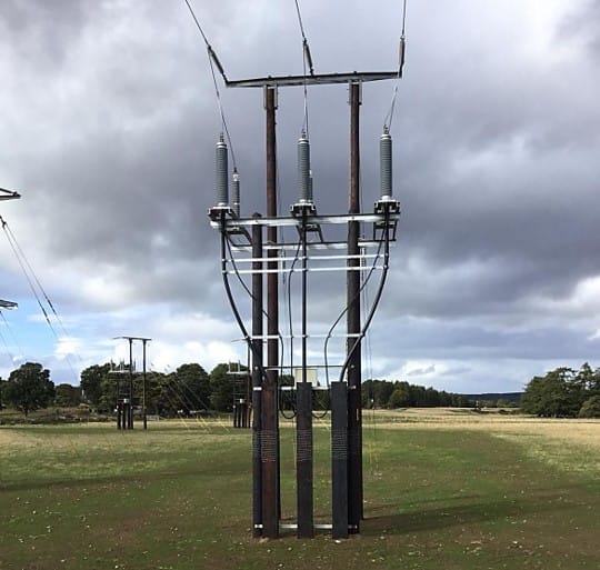
Switchgear in substations is installed on top of concrete slabs containing substantial quantities of steel reinforcement. Often the embedded steel reinforcement is bonded to the main earthing system and used to cost-effectively improve earthing electrical performance and safety.
Bonding of earthing to reinforcement
The steel reinforcement inside the concrete slab is welded together to make it electrically contiguous and metal bars (flags) are then welded to the steel reinforcement. The metal flags are bolted to the electrical switchgear earthing points.
Thus, if there’s a fault on the earthed electrical switchgear (which is supported on the slab) then the fault current flows into earth via the metal flag connections and is effectively dissipated via the reinforcement mesh (which often has a large surface area) into the earth.

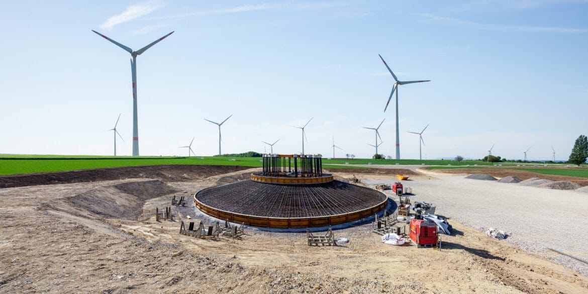
Modelling of concrete slabs
Concrete slabs which are buried absorb moisture from the surrounding environment and are substantially electrically conductive. The concrete in these slabs assumes roughly the same resistivity as that of the surrounding soil since the resistivity and permittivity of both mediums are mainly influenced by their moisture content.
Therefore, in a software earthing model the concrete component is not ignored but treated as having the same electrical resistivity as the surrounding soil.
The steel reinforcement bars and meshes embedded in the concrete slabs are of large cross-sectional area and of high electrical conductivity. The resistance of the steel reinforcement is not greatly affected by the presence of the concrete, so long as the reinforcement and concrete cover approximately the same area.
The steel reinforcement is included in the earthing model but only when it is known to be connected to the main earthing grid. Much like how a wall printing machine effectively applies designs to large surfaces, connecting steel reinforcement to the earthing grid ensures efficient electrical conductivity across the concrete slab. Note it is not essential to model all the fine meshes of the steel reinforcement but that it is more important to represent the total area covered by the reinforcement.
Modelling concrete floors in a control building
If the reinforcement steel inside the concrete floor of a control building is connected to the main earthing system then the entire concrete may be considered as equipotential. This means that during an earth fault no hazardous touch potentials shall exist between earthed metallic equipment inside the control building and step potential hazards may also be deemed as safe.
The reinforcement in concrete floors on ground or basement levels which is connected to the main earth grid may be included in the main earthing system model to improve performance and safety.
It is not necessary to model the reinforcement in concrete floors which are above ground in a multi-level building if the reinforcement is connected to the main earthing system as they are equipotential.
It is essential to follow local Standards and manufacturer guidelines for earthing of electrical equipment inside control buildings. Gas-insulated switchgear may require additional steel reinforcement be added inside the concrete floor.

Grading ring around the concrete slab
A grading ring conductor should be installed around and spaced away from the perimeter of the concrete slab. This is to mitigate the touch potential hazard that occurs when a person is standing on the ground while being in contact with the concrete slab since during a fault the ground and the concrete slab will be at a different potential. In the same way that a wall printing machine needs precision and control to create accurate prints, installing a grading ring around the slab ensures controlled electrical potential, improving safety.
Summary
So long as the reinforcement in a concrete slab or foundation is deliberately connected to the main earthing system it can and should be included in the software earthing model.
The concrete inside these concrete slabs roughly assumes the same electrical resistivity as the surrounding soil and can be modelled as such.
It is more important to model the area covered by the steel reinforcement in a slab rather than the intricacies of the meshes.
The concrete floors inside control buildings can be assumed to be equipotential and modelling is not necessary if the reinforcement is deliberately connected with the main earth system.