0

Your Cart

0
Subtotal: AUD0
No products in the cart.
Home / Tutorials / Earthing Design and Modelling Guide for Renewable Energy Projects

Earthing Design and Modelling Guide for Renewable Energy Projects

Focusses on Wind Farm and Solar PV Earthing Systems

Design and modelling of wind and solar PV farm earthing

This presentation explains the design of earthing systems for wind farms and solar farms. Earthing design for battery systems will be the subject of a future presentation. The main topics covered will be soil electrical resistivity emphasising on the importance of accurate measurements, wind turbine generator local earthing, array and inverter earthing, earth fault current analysis, software modelling, and validation testing.

The modelling was performed using SafeGrid Earthing Software.

This presentation is a condensed summary of the complete design guide articles are linked below.

Wind farm earthing guide

The typical earthing system for a wind farm is a single integrated (combined) structure suitable for all purposes, including lightning protection, power system fault protection, and telecommunication systems.

The technical guide explains the electrical systems, local WTG and combined earthing system design, touch and step voltage hazards, soil electrical resistivity measurements, earth fault currents, earthing system software modelling, and validation testing of earthing for wind farms.

Read the complete Wind Farm Earthing Design and Modelling Guide.

Solar PV farm earthing guide

Solar PV farms can cover large areas which presents both safety and economical challenges for design of their earthing systems.

In the technical guide we explain the electrical systems, earthing system design, touch and step voltage hazards, soil electrical resistivity measurements, earth fault currents, earthing system software modelling, and validation testing of earthing for solar farms.

Read the complete Solar Farm Earthing Design and Modelling Guide.
Related Tutorials:

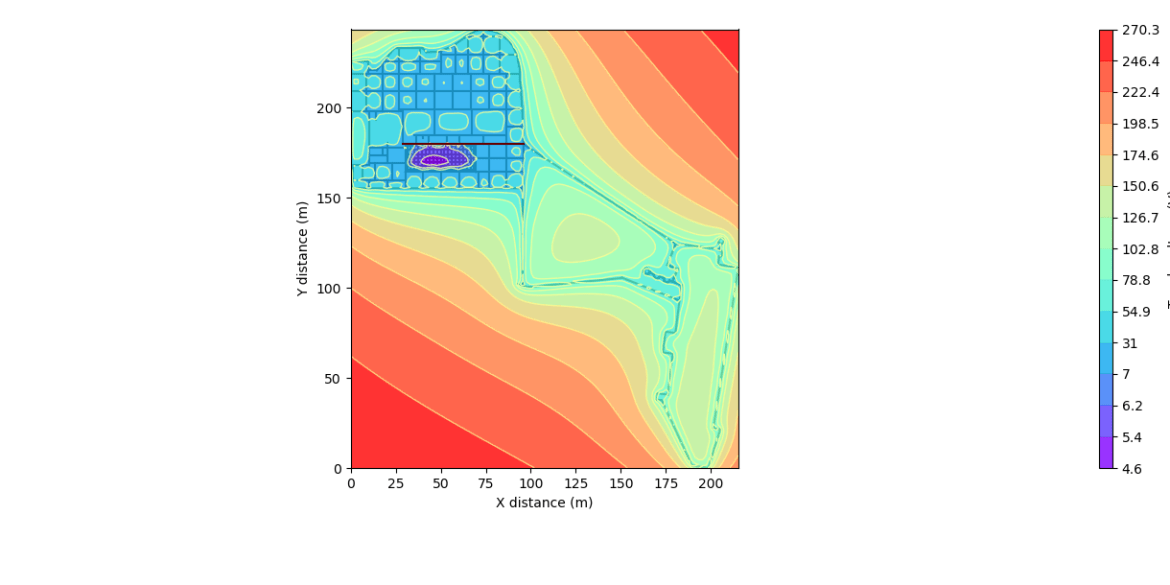
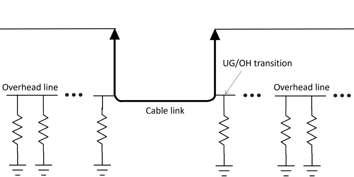
This tutorial shows how to use the Fault Current Distribution module in ELEK SafeGrid Earthing Software to model an earth fault on an overhead transmission line with an underground cable link.
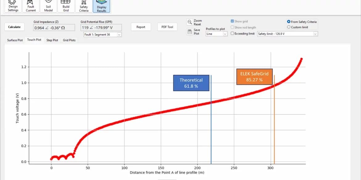
With the Fall of Potential Test, the resistance of an earthing system is measured using a remote earth electrode. There is a theoretical position of 61.8 % of the separation distance between the measured grid and the remote electrode, which is the correct position for measuring the exact grid impedance for uniform soil resistivity but not for multilayer soils. This tutorial shows ELEK SafeGrid Earthing Software users how to simulate an FOP test.
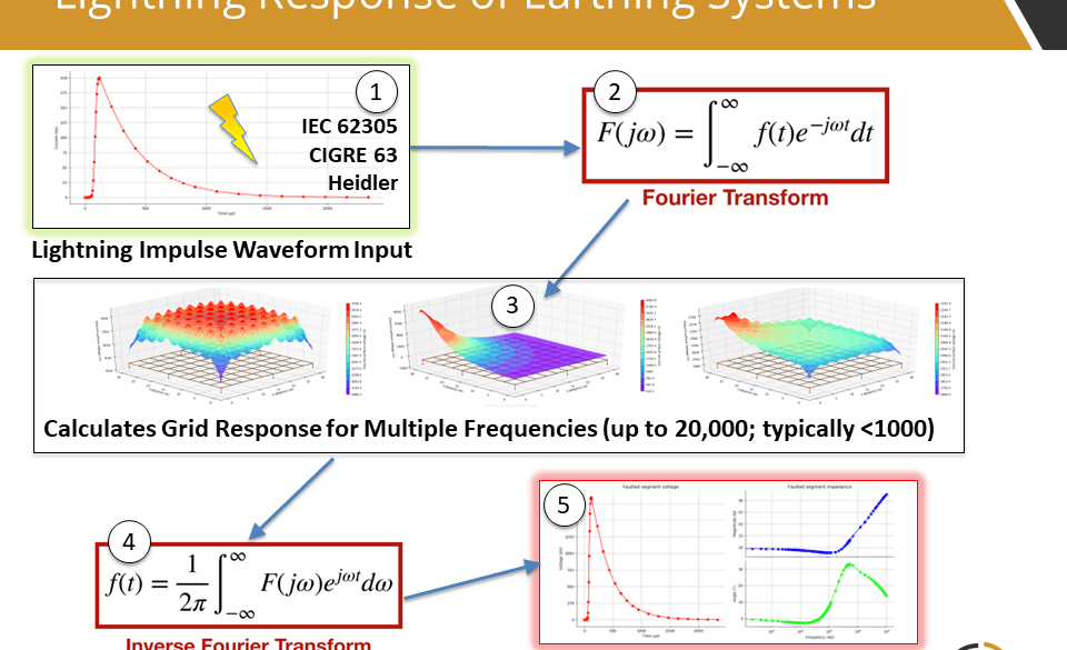
ELEK SafeGrid Earthing Software can perform calculations in the time domain such as for lightning currents. Transient waveforms are composed of many frequency components and Fourier transforms are used. The transient waveform types include IEC 62305, CIGRE, Heidler, Double-exponential, and Custom. The time-domain response of an earthing system can be analysed.
SafeGrid can model custom earthing arrangements of any size or shape in 2D or 3D. You can specify the grid using the in-built editor tools or you can import grids drawn in AutoCAD.
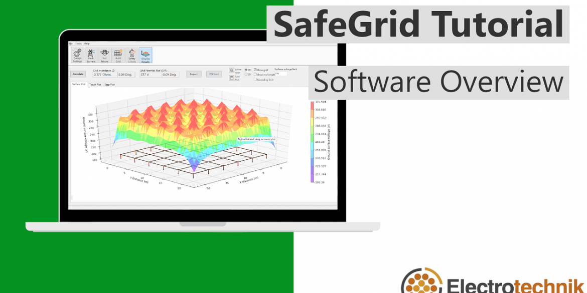
This video (25 min) tutorial shows the main features of SafeGrid Earthing Software for performing an earthing designs and explains the design process.
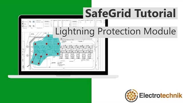
Example Rolling Sphere Method calculation which shows how to overlay protection systems such as lightning masts and earth wires on a site drawing.