How do you perform a Protection Coordination Study?
Protection coordination aims to strategically deploy protective devices to minimise damage and effectively isolate faults within an electrical system. Conducting a protection coordination study is essential to ensure the proper alignment of all protective devices.
The steps in this guide are demonstrated using ELEK Cable Pro Web, which includes a full library of manufacturer devices from Schneider, ABB, and others. If you’d like to explore protection coordination, our free Protection Coordination Calculator lets you add generic protective devices, plot their time-current curves, and check for coordination — making it a great way to get familiar with the process and the principles covered in this article.

Step 1 - Selection of protective devices
, and various dropdown and input options.")
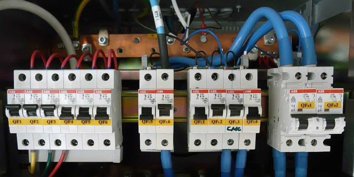
First, select the upstream breaker. Click Add to add the devices. We have chosen Schneider as the manufacturer for the upstream breaker.
Next, select the family, model, and rating. For the Trip unit, we have chosen Micrologic 5.0-distribution protection. Click Accept to save the changes and add the device.
Next, we add the downstream device in the same way. An ABB device has been added as the downstream device. To achieve coordination, ensure the downstream devices have a lower rating than the upstream devices.
Step 2 - Coordination
 on the y-axis and current (A) on the x-axis, both on logarithmic scales.")
In coordination, we can see that the curves overlap. To achieve coordination, enough separation must exist and be maintained between the TCC curves.
Step 2.1 - Coordination criteria tool

The standards in AS/NZS 3000:2018, clause 2.5.7.2.3 specify a current multiplying factor of 1.5, which we can show as an imaginary line on the plot using Coordination criteria. This will work as a guideline for coordinating the upstream device.
Click on Add and select the downstream device. Add the current multiplier of 1.5. This will add the imaginary curve in the plot. To achieve coordination, we have to move the curve of the upstream device to the right-hand side of the imaginary curve.
Step 3 - Protective device settings

Select the upstream device. Adjust the long and short-time protection pick-up currents and time delay so that the upstream device curve clears the blue curve, which is our coordination criteria.
Step 5 - Sequence of operation

You can also see the sequence of operation for the arching fault current. In the Sequence of operation tab, enter the fault current. Here, after adding the fault current to 4320 A, we can see that the tripping time of the downstream device is 0.019 seconds, and for the upstream device, it is 9.522 seconds. This means that the devices are coordinated.