How to size DC power cables
In this article, the cable sizing calculations are carried out according to Standard AS/NZS 3008.1 which is similar to IEC Standards. This standard defines electrical properties of cables under typical Australian conditions and installation arrangements. It applies to alternating current (AC) systems up to and including 0.6/1.0 kV. Despite its title including “alternating voltages,” this standard can be applied to direct current (DC) installations. AS/NZS 3008.1 satisfies the circuit requirements, including the current-carrying capacity, voltage drop, and short-circuit temperature limit, and simultaneously minimizes the costs of the entire photovoltaic (PV) system.
DC cable sizing has considerable implications on the performance, total cost, and safety of PV systems. In addition, compliance with pertaining standards needs to be guaranteed. This article considers current rating and voltage rise calculations in DC cables.
Differences between DC and AC Cables
DC cables are widely used in solar power plants. Indeed, the construction of DC cables is entirely different from that of AC cables. Copper is the major material used in DC cables because of its high flexibility, current-carrying capacity, and thermal performance. Moreover, copper per unit length of DC cables is different from that of AC cables owing to the lack of skin effect in DC cables; therefore, the power evacuation capability of DC and AC cables are different, and thus AC cables must not be used for DC power evacuation. Indeed, DC cables do power evacuation different from AC cables. This work focuses on the sizing of DC cables for PV system applications in accordance with AS/NZS 3008.1. In addition, it is assumed that two segments of DC cables are the PV string to the array junction box (AJB) and AJB to the inverter.
Nomenclature
| Icable(PV string to AJB) | DC cable rating current – From PV string to AJB |
| IPV module at MPP | Rated PV current at maximum power point |
| DF | Derating factor |
| Icable (AJB to inverter) | DC cable rating current – From AJB to inverter |
| Imax DC inverter input | Maximum DC inverter input current |
| ISC max PV Mod | Maximum short-circuit PV module current |
| ISC PV Mod | Short-circuit PV module current |
| αi | Temperature coefficient of short-circuit PV module current |
| βv | Temperature coefficient of open-circuit PV module voltage |
| VOCPVMod | Open-circuit PV module voltage |
| Tcell max | Maximum cell temperature |
| Vrise DC cable | Voltage rise of all the DC cable – From PV string to inverter |
| Vrise string to AJB | Voltage rise of DC cable – From PV string to AJB |
| Vrise AJB to inverter | Voltage rise of DC cable – From AJB to inverter |
| VPV string | Voltage of PV string |
| VPV module at MPP | Rated voltage of PV module at maximum power point |
| NPV / string | Number of PV modules in string |
| VMPPT inverter min | Minimum MPPT inverter input voltage |
| VMPPT inverter max | Maximum MPPT inverter input voltage |
| VPV Mod min | Minimum PV module temperature at Tcell max |
| VPV Mod max | MaximumPV module temperature at Tcell min |
| Tcell max | Maximum cell temperature |
| Tcell min | Minimum cell temperature |
| Tambient min | Minimum ambient temperature |
| Tambient max | Maximum ambient temperature |
| NOCT | Nominal cell operation temperature |
| G | Average hourly plane of array irradiance (W/m²) |
| Lcable from PV string to AJB | Length of the DC cable from PV string to AJB |
| Istring at MPP | PV string current at maximum power point |
| Lcable(AJBtoinverter) | Length of the DC cable from AJB to inverter |
| Iarray at MPP | PV array current at maximum power point |
- Power (W): AC power of the PV system.
- Voltages (V): Voltages of PV module (rated and open-circuit voltages) and inverter (minimum and maximum MPPT voltages)
- Current (kW, kVA, A): Currents of PV module (rated and short-circuit currents) and inverter(maximum input DC current)
- Temperatures (°C): The maximum and minimum ambient temperature in the located site.
- Distance (m, ft): Estimated cable or wire length in meters or feet.
- Cable type: Number of cores in the cable. Ignore the neutral and earth conductor in three phase cables.
- Insulation type: Typically, Thermoplastic (PVC) or Thermoset (XLPE). Correct selection of the temperature rating is crucial.
- Number of parallel cables: Typically, only one cable. More than one cable may be selected for high-load scenarios. If the cable type is single core, this parameter means sets of cables; for instance, six cables are considered if two parallel cables for a “three single-cores” type cable is selected.
- Cable installation: The worst-case section of the cable installation must be considered.
1. Current rating calculation
In PV systems, two DC circuits exist; the first circuit is between the PV string to AJB and the second segment is between AJB and the inverter.
The current rating of DC cables for the first segment is obtained considering the following conditions:
Condition 11: The cable rating current should be equal to or greater than the PV string current; thus,

Condition 12: The selection of cable rating should be based on the allowable ambient and ground temperatures. Typically, designing tables use the ambient and ground temperatures as 40 and 25°C, respectively.
Condition 13: The selection of current rating should be based on the cable type, insulation type, and cable installation method.
According to the above conditions and in some cases, a de-rating factor (DF) is considered in the designing tables (Tables 22–27 in AS/NZS 3008). As for cables with a DF, the cable rating current calculation in Condition 11 should be updated as follows:

Accordingly, Conditions 12 and 13 should be followed to select a proper cross-section area based on the new inverter current. At this stage, an initial cross-section of the first segment can be selected.
The second segment of DC cables is between AJB and the inverter. The current rating of the second segment can be obtained based on the following conditions:
Condition 21: The cable rating current should be equal to or greater than the summation of inverter AC current and load current; thus,


where,

Condition 22: The selection of the cable rating should be based on the allowable ambient and ground temperatures. Typically, designing tables use the ambient and ground temperature as 40 and 25°C, respectively.
Condition 23: The selection of current rating should be based on the cable type, insulation type, and cable installation method.
According to the above conditions and in some cases, a de-rating factor is considered in the designing tables (Tables 22–27 in AS/NZS 3008). As for cables with a DF, the cable rating current calculation in Condition 21 should be updated as follows:

Accordingly, Conditions 22 and 23 should be followed to select a proper cross-section area based on the new inverter current. At this stage, an initial cross-section of the second segment (consumer mains DC cable) can be selected. After sizing the first and second segments of the DC cable, the voltage rise calculation should be carried out to confirm that the selected DC cables secure the aimed DC voltage rise.
2. Voltage rise calculation
The voltage rise of the selected cables are calculated after selecting the cross-section of cables using the current ratings. The DC voltage rise (Vrise DC cable) from the PV string to the inverter can be calculated as follows:


Where VMPPT inverter max and VPV Mod min can be calculated as:


Accordingly, the Tcell min and Tcell max can be calculated using the cell temperature equation based on the minimum and maximum ambient temperatures, as follows:


where,


where,

Therefore, the V drop DC cable ≤ calculated value using Eq.(7);otherwise, the length of DC cables from the PV string to AJB and/or that from AJB to the inverter should be increased to secure the required voltage rise.
The following example is included to clarify the application of standard methods in real life cases.
Example 1: AC output power from a PV system is required to be 82.8 kW. The following data is available from the site:
- ABB inverters
- Generic PV modules of 250Wp
- Latitude = 97 and Longitude = 35.91
- Daily location irradiation on the tilted surface =5.93 kWh/m²
- Total length of DC cable= 70 m
- Maximum ambient temperature= 40 °C
- Minimum ambient temperature =-5 °C
Proper sizing of DC cables for this example is required.
Solution:
- The AC output power is equal to 8 kW.
- Base on the availability of the ABB inverters, appropriate inverters which are combatable to this output are 50 kW (TRIO-50.0-TL-OUTD) and 33 kW (PRO-33.0-TL-OUTD), which are three-phase inverters.
- The power of PV module should be 250 Wp. Thus, Trina Solar TSM-250-PC-PA05A may be used in this example.
- DC cable from the PV string to AJB= 2 m
- DC cable from AJB to the inverter= 10 m
- Two DC cables are of single-core type
- Insulation type is thermoplastic (PVC)
- Cable installation is wiring enclosure in air
1. Current rating calculation:
1.1. From PV string to AJB
The rated current of the PV module at STC is equal to 8.2 A. Therefore, the cable current must be equal or greater than the rated current of the PV module. Thus,

Therefore,
Based on the rated current of the PV module, cable type, and installation condition, the cross-section area is selected from AS/NZS 3008.1.1:2017, Table 10, Column 11; thus, the proper cross-section of the DC cable from the PV string to AJB is 4 mm².
1.2. From AJB to inverter
The second segment connects AJB to the inverter. In this example, two inverters require two different DC cables from both arrays to these inverters based on the inverter ratings.
A. 50 kW inverter (TRIO-50.0-TL-OUTD) / Array 1
The number of strings in parallel is calculated as follows:

According to the PV module datasheet, ISC = 8.9 A,Tc of Isc = 0.053%/°C, TMaxcell and= 56.060525 °C.
Thus,


As the inverter can load 120% of its total capacity, the maximum power is 60 kW. As the number of string is assumed to be 26 PV modules/string, the total voltage at the MPP is 793 V. Therefore, the required current to cover the maximum power is 75.7 A. Thus, the required number of strings in parallel is 9.22. Therefore,
In this array, ten strings form the PV array. Therefore, it is recommended to use an AJB with a dimension of 10 mm ×4 mm as input. Furthermore, the cross-section area of the output cable from AJB can be calculated as follows:

Thus,

Based on the rated current of the PV module, cable type, and installation condition, the cross-section area is selected from AS/NZS 3008.1.1:2017, Table 10, Column 11; thus, the proper cross-section of the DC cable for this array (AJB to DC switch) is 25 mm².
B. 33 kW (PRO-33.0-TL-OUTD) / Array 2
The number of strings in parallel can be calculated as follows:

According to the PV module datasheet, ISC = 8.9 A, Tc of Isc = 0.053%/°C, TMaxcell and = 56.060525 °C.
Thus,


As the inverter can load 120% of its total capacity, the maximum power is 39.6 kW. As the number of string is assumed to be 27 PV modules/string, the total voltage at the MPP is 823.5 V. Therefore, the required current to cover the maximum power is 48.1 A, and the required number of strings in parallel is 5.86. Thus,

In this array, six strings form the PV array. Therefore, it is recommended to use an AJB with a dimension of 6 mm ×4 mm as input. Furthermore, the cross-section area of the output cable from AJB can be calculated as follows:

Based on the rated current of the PV module, cable type, and installation condition, the cross-section area is selected from AS/NZS 3008.1.1:2017, Table 10, Column 11; thus, the proper cross-section of the DC cable for this array (AJB to DC switch) is 10 mm².
2. Voltage rise calculation:

According to AS/NZS 3008.1.1:2017, the voltage drop for the cable with a cross-section of4 mm² is 14.3 V/A.km. As the PV module current at MPP is equal to 8.2 A and DC cable length from the string to AJB is supposed to be 2 m, the voltage drop from the PV string to AJB (Vdrop, string to AJB) is equal to 0.235 V in both arrays.
In this example, the daily location irradiation on the tilted surface is equal to 5.93 kW/m². Thus, the average solar irradiation (𝑆) is 494.17 W/m².
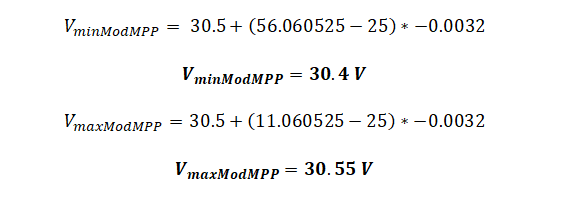
The minimum and maximum ambient temperatures in this site are -5 and 40 °C, respectively. In addition, nominal operating cell temperature (NOCT)= 46 °C. Subsequently, the minimum and maximum cell temperatures can be obtained as follows:

Moreover ,VMPP = 30.5 V, Tc of voc=-0.32%/°C, and provided the minimum and maximum cell temperatures, the minimum and maximum module voltages at MPP can be calculated as follows:
A. 50 kW inverter (TRIO-50.0-TL-OUTD) / Array 1
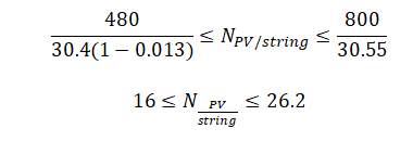
It is assumed that the PV modules will be on the range of the MPPT voltage; thus, the average PV string voltage is 640 V, and the design voltage drop is equal to 1.3%.
Consequently, the length of the string (number of PV modules per string) can be obtained as follows:
Thus,
In this array, the cross-section of the DC cable for this array (AJB to DC switch) is 25 mm². According to AS/NZS 3008.1.1:2017, the voltage drop for a cross-section of 25 mm² is 2.23 V/A.km. As the string current at MPP is equal to 8.2 A and DC cable length from AJB to the inverter is 10 m, the voltage drop from AJB to the inverter (Vdrop,AJB to inverter ) is equal to 0.128 V.
For this inverter, the number of PV modules per string is 26, and the voltage for each PV module at MPP is 30.5 V.
Thus,
Thus,

Eq. (8) is used to calculate the voltage drop per each string, as follows:

B. 33 kW (PRO-33.0-TL-OUTD) / Array 2
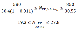
According to the datasheet of PRO-33.0-TL-OUTD, VminMPPT,inverter = 580 V and the VminMPPT,inverter = 850 V.
It is assumed that the PV modules will be on the range of the MPPT voltage; thus, the average PV string voltage is 715 V, and the design voltage drop is equal to 1.1%.
Consequently, the length of the string (number of PV modules per string) can be obtained as follows obtained using equation (1) as follows:
Thus,
In this array, the cross-section of the DC cable for the array (AJB to DC switch) is 10 mm². According to AS/NZS 3008.1.1:2017, the voltage drop for a cross-section of 10 mm² is 5.46 V/A.km. As the string current at MPP is equal to 8.2 A and DC cable length from AJB to the inverter is 10 m, the voltage drop from AJB to the inverter (Vdrop,AJB to inverter) is equal to 0.448 V.
For this inverter, the number of PV modules per string is 27, and the voltage for each PV module at MPP is 30.5 V.
Thus,

Eq. (8) is used to calculate the voltage drop per each string, as follows:


