Table of Contents
Introduction
The AC resistance of a cable conductor is always larger than the DC resistance. The primary reasons are ‘skin effect’ and ‘proximity effect’, discussed in more detail below. DC resistance is more readily available than AC resistance because AC resistance depends on variables related to the installation of the cables. Accurate AC resistance is essential for high voltage current rating, voltage drop, fault current, and power loss calculations.
The steps for calculating AC resistance for conductors in cables are as follows. The same method is applicable for calculating the AC resistance of conductors, screens, sheaths, or armours.
- Obtain the DC resistance at a reference temperature.
- Adjust the DC resistance for the actual operating temperature.
- Calculate the skin effect factor.
- Calculated the proximity effect factor.
- Calculate AC resistance.
The calculation equations are included in this report, along with two worked examples. The examples below indicate the effects of the skin and proximity effects on resistance are significant – AC resistance was approximately 20 % higher than DC resistance for both examples.
ELEK Cable HV Software™ was used for the example calculations.
DC Resistance of Cables
The DC resistance of a cable refers to the inherent electrical resistance that the cable exhibits when direct current (DC) flows through it. The DC resistance of a cable is primarily influenced by factors such as the material used for the conductor (e.g., copper or aluminium), the conductor’s cross-sectional area, and the cable’s length, as well as the conductor’s temperature. The resistance is directly proportional to the length of the cable and inversely proportional to the cross-sectional area. Longer cables or cables with smaller cross-sections will have higher DC resistance, resulting in greater voltage drop and power losses.
The DC resistance for a cable conductor can be measured or calculated. Standard DC resistance 20\(^{\circ }C\) values for cable conductors are obtained from IEC 60228 (metric sizes) or IEC 62602 (imperial sizes).
Typically, the values of conductor DC resistance are provided for a reference operating temperature. The actual DC resistance of the conductor will be affected by its operating temperature, which is determined by how much current the conductor is carrying.
The equation for calculating conductor DC conductor resistance at operating temperature, R’ is:
\(R’ = R_o [1+\alpha_{20}(\theta_{n}-20)]\)
Where
\(R_o\) is the conductor DC resistance \( \left(\Omega/m\right)
\) at \(20^{\circ }C\)
\(\alpha_{20}\) in the conductor temperature coefficient at \(20^{\circ }C\) per Kelvin
\(\theta_n\) is the operating temperature \((^{\circ }C) \) of each conductor
AC Resistance
The AC resistance of a cable refers to the effective resistance that the cable presents to the flow of alternating current (AC). Unlike direct current (DC), where resistance remains constant, the resistance of a cable carrying the AC current is influenced by the skin effect and proximity effect.
To calculate the AC resistance of a cable, the skin and proximity effect must be considered. Standards like IEC 60287-1-1 [ref. 1] provide methods and formulas to determine the skin and proximity effect factor and convert the DC resistance to an equivalent AC resistance for accurate cable rating calculations.
The equation for AC resistance, which takes into account skin effect and proximity effect, is as follows:
Where:
R = the AC resistance \( (\Omega/m)
\) per unit length of the conductor at its operating temperature
R’ = the DC resistance \( (\Omega/m)
\) per unit length of the conductor at its operating temperature
\( y_{s} \) = skin effect factor
\( y_{s} \) = proximity effect factor
Calculating the AC resistance requires the calculation of the skin and proximity effect factor.
Skin Effect in AC Cables
The skin effect is a phenomenon in AC conductors that causes the current to distribute unevenly across the cross-sectional area of a conductor. AC currents concentrate near the conductor’s surface at higher frequencies, while the conductor’s core carries less current. As a result, the resistance of the cable increases due to the reduced effective cross-sectional area involved in carrying the current.
Hollow conductors are often used at very high frequencies for this reason. At power frequencies (typically 50 or 60 Hz), while less pronounced, the change in resistance due to the skin effect is still noticeable.
The equation for the skin effect factor is as follows:
For \( 0\lt x_{s}\le 2.8 \) \( y_s=\frac{x_s^4}{192+0.8x_s^4} \)
For \( 2.8\lt x_{s}\le 3.8 \) \( y_s=-0.136-0.0177x_s+0.0563x_s^2 \)
For \( x_{s}\gt 3.8 \) \( y_s=0.354x_s+0.733\)
Where:
\( x_s^2=\frac{8\pi f}{R^\prime}{10}^{-7}k_s \)
f is the supply frequency in Hertz
Values of ks are given in Table 3.
Proximity effect
The proximity effect in cables refers to the phenomenon where the proximity of other conductors or nearby magnetic fields influences the electrical characteristics of a cable. Its effects are that it increases resistance and is more prominent at higher frequencies. In simple terms, when conductors are close together, their current distribution can be uneven due to the magnetic fields they generate. This can lead to increased resistance and other electrical effects.
The equation for the proximity effect factor is as follows
\( \begin{aligned}
y_p =\cfrac{x_p^4}{192+0.8x_p^4} \bigg(\cfrac{d_c}{s}\bigg)^2
\left[\begin{matrix}0.312\bigg(\cfrac{d_c}{s}\bigg)^2 +\cfrac{1.18}{\cfrac{x_p^4}{192+0.8x_p^4} + 0.27}\end{matrix}\right]
\end{aligned} \)
Where:
\( x_p^2 = \frac{8\pi f}{R’}10^{-7} k_p \)
f is the supply frequency in hertz
Values of kp are given in Table 3.
AC Resistance Calculations
Example 1 - Single-core cable
Table 1: Single-core cable parameters
| Parameter | Value | Units |
|---|---|---|
| Frequency | 50 | Hz |
| Number of cores | 1 | |
| DC resistance at 20 degrees | 0.0000283 |
|
| Skin effect coefficient (ks) | 1 | |
| Proximity effect coefficient (kp) | 1 | |
| Phase spacing /core diameter | 500 | mm |
| Conductor size | 630 | mm2 |
|
Temperature coefficient of resistance |
0.00393 | 1/K |
| Conductor diameter | 30.3 | mm |
| Operating temperature | 90 |
|
Conductor DC resistance at operating temperature, R’
Argument for calculating skin effect xs
\)
Skin effect factor, ys
)^4}{192+0.8\times(1.866123061
)^4} \)
Argument for calculating proximity effect, xp
}10^{-7} \times1 \)
\)
Proximity effect factor, yp
y_p =\cfrac{x_p^4}{192+0.8x_p^4} \bigg(\cfrac{d_c}{s}\bigg)^2
\left[\begin{matrix}0.312\bigg(\cfrac{d_c}{s}\bigg)^2 +\cfrac{1.18}{\cfrac{x_p^4}{192+0.8x_p^4} + 0.27}\end{matrix}\right]
\end{aligned} \)
\)
The AC resistance R at operating temperature of the cable conductor is
\times[1+0.06012448972
+0.000789475
] \)
\)
In summary, the skin effect and proximity effects increase conductor resistance by 18.66 % and 0.07 %, respectively. The AC resistance of the conductor is 118.98% of the DC resistance at operating temperature.
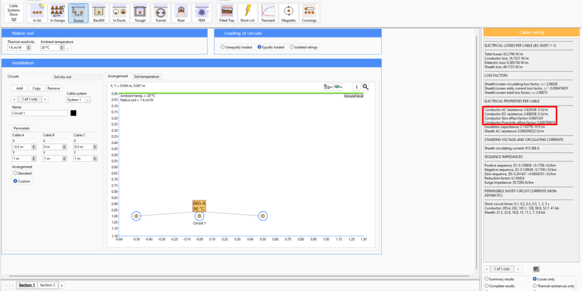
The AC resistance calculations of power cables are automatically calculated using ELEK Cable High Voltage software. The image below shows that we have matching results.

Example 2 - Multi-core cable
Table 2: Multi-core cable parameters
| Parameter | Value | Units |
|---|---|---|
| Frequency | 50 | Hz |
| Number of cores | 3 | |
| DC resistance at 20 degrees | 0.0000283 |
|
| Skin effect coefficient (ks) | 1 | |
| Proximity effect coefficient (kp) | 1 | |
| Phase spacing /core diameter | 62.1 | mm |
| Conductor size | 630 | mm2 |
|
Temperature coefficient of resistance |
0.00393 | 1/K |
| Conductor diameter | 30 | mm |
| Operating temperature | 90 |
|
Note:
For multi-core cables, phase spacing (s) is the distance between the centre of the two conductors or the diameter of the last layer of each core.
For this example, the diameter of the last layer of each core is 62.1 mm, which is the phase spacing (s).
Conductor DC resistance at operating temperature, R’
\ \Omega/m \)
The argument for calculating skin effect xs
}{10}^{-7}\times1 \)
\)
Skin effect factor, ys
\( =\frac{(1.8661201029)^4}{192+0.8\times(1.8661201029)^4} \)
\)
The argument for calculating proximity effect, xp
\)
Proximity effect factor, yp
y_p =\cfrac{x_p^4}{192+0.8x_p^4} \bigg(\cfrac{d_c}{s}\bigg)^2
\left[\begin{matrix}0.312\bigg(\cfrac{d_c}{s}\bigg)^2 +\cfrac{1.18}{\cfrac{x_p^4}{192+0.8x_p^4} + 0.27}\end{matrix}\right]
\end{aligned} \)
\right)_{}^4}{192+0.8\left(1.8661201029
\right)_{}^4}+0.27}\bigg]\)
\( =0.0511765348 \)
The AC resistance R at operating temperature for cable with magnetic armour
\ \Omega/m
\)
In summary, the skin effect and proximity effects increase conductor resistance by 6.01 % and 5.12 %, respectively. Since the magnetic armour of the cable interferes with the inner metallic layers, a constant 1.5 as specified in IEC 60287-1-1 [ref. 1] is multiplied with the skin and proximity effects to obtain conservative results. The AC resistance of the conductor is 116.69% of the DC resistance at operating temperature.
The AC resistance calculations of power cables are automatically calculated using ELEK Cable High Voltage Software™. The image below shows that we have matching results.

Table 3: Skin and proximity effects – Experimental values for the coefficients ks and kp [ref. 1]
| Type of conductor | Conductor insulation system | Ks | Kp |
|---|---|---|---|
| Copper | |||
| Round, solid | All | 1 | 1 |
| Round, stranded | Fluidd/papere/PPLf | 1 | 0.8 |
| Round, stranded | Extruded9/Mineralh | 1 | 1 |
| Round, Millikenc | Fluid/paper/PPL | 0.435 | 0.37 |
| Round, Milliken, insulated wiresb | Extruded | 0.35 | 0.20 |
| Round, Milliken, bare uni-directional wiresb | Extruded | 0.62 | 0.37 |
| Round, Milliken, bare bi-directional wiresb | Extruded | 0.80 | 0.37 |
| Hollow, helical stranded | All | a | 0.8 |
| Sector-shaped | Fluid/paper/PPL | 1 | 0.8 |
| Sector-shaped | Extruded/Mineral | 1 | 1 |
| Aluminium | |||
| Round, solid | All | 1 | 1 |
| Round, stranded | All | 1 | 0.8 |
| Round Milliken | All | 0.25 | 0.15 |
| Hollow, helical stranded | All | a | 0.8 |
a The following formula should be used for ks:
\( k_s=\left(\frac{d_c^\prime-d_i}{d_c^\prime+d_i}\right)\left(\frac{d_c^\prime+2d_i}{d_c^\prime+d_i}\right)^2\)
Where
di is the inside diameter of the conductor (central duct)(mm);
d’c is the outside diameter of the equivalent solid conductor having the same central duct (mm)
References:
[1] IEC 60287-1-1 “Electric cables – Calculation of the current rating, Part 1-1: Current rating equations (100 % load factor) and calculation of losses – General” (2023).
[2] IEC 60228 “Conductors of insulated cables” (2023).
[3] IEC 62602 “Conductors of insulated cables – Data for AWG and KCMIL sizes” (2009).


