0

Your Cart

0
Subtotal: AUD0
No products in the cart.

Practical Guide to Selective Protection Coordination

Practical Guide to Selective Protection Coordination

Setting Priorities and Adjusting Protective Devices for Reliable Fault Isolation

Table of Contents

What is Selective Coordination?

Selective coordination refers to the strategic arrangement and setting of protective devices (such as circuit breakers, fuses, and relays) within an electrical system to ensure that only the device closest to the fault operates while the rest remain unaffected.

This approach isolates the faulted section quickly and minimises disruption to the remaining parts of the electrical network. By carefully adjusting the time-current characteristics of each device, selective coordination ensures that faults are managed hierarchically, enhancing the electrical system’s reliability and safety while preventing unnecessary outages and equipment damage.

Selective Coordination in Action

Consider the electrical network example shown in the figure below. If there is a fault downstream of protective Device 7, the fault current will be fed from the upstream supply.

Selective coordination results in only Device 7 opening to isolate the fault from its source. All other devices shown would remain closed to maximise service continuity and minimise load disruption.

Diagram illustrating a sequence of blocks and arrows, showing progression from input signal to fault labeled with a lightning bolt icon.
Figure 1 - Selective coordination for a fault downstream of Device 7

Devices are selected and set to achieve selective coordination so that downstream devices operate faster than upstream devices. Remember that coordination will rarely, if ever, be perfect. That is why setting the prioritisation of tripping is necessary.

Let’s take a closer look at selective coordination by comparing the time-current curves of two devices that are in series. The tripping curve of Device 1 is located to the right of Device 2 on the time-current curve.

For a fault downstream of Device 2, due to selective coordination, the following occurs:

  • For a fault current of 120 A (Ifault1), the trip time of Device 2 is around 1.5 seconds, while the trip time for Device 1 is around 1000 seconds.

  • For a fault current of 220 A (Ifault2), the trip time of Device 2 is around 0.15 seconds, while the trip time for Device 1 is around 2.5 seconds.

Graph and diagram showing two devices’ protection curves on a log-log plot (left) and a power distribution fault scenario with arrows indicating fault current paths (right).
Figure 2 - Selective coordination of two protective devices

Note from the time-current curve if the fault current exceeds 1000 A then selective coordination cannot exist. In this scenario, it is uncertain which device would trip first, and both Device 1 and Device 2 would likely trip and/or be damaged.

Setting Priorities for Tripping

In typical installations, several protective devices are along the path between the fault location and the source. This makes selective coordination difficult, if not impossible, in most situations. The image below shows the overlapping time-current curves of several devices in the series, which means that under certain fault conditions, multiple devices will trip simultaneously.

Screenshot of an electrical protection coordination tool showing a single line diagram on the left and overlapping time-current curves highlighted on the graph to the right.
Figure 3 - Typical set of overlapping time-current curves of circuit breakers that are in series in an electrical network

There is a logical method for prioritising protective devices, which can improve the reliability of your electrical network. Setting priorities for protective device tripping will ensure that faults are effectively isolated while minimising disruptions to the rest of the system.

There is a relatively simple priority system with two priority levels: If you must intentionally miscoordinate any protective devices, they should be Level 2 priority.

Device Priority

Description

Level 1 – Higher priority

Protective devices are typically on a mains circuit with multiple feeders. If the Level 1 priority device trips, you lose more than one circuit.

A diagram with three squares connected by arrows; the top square is red, the bottom left square is white, and the bottom right square is red.
Figure 4 - Level 1 priority protective device

In this case, you must have good selectivity between the feeder and mains devices.

Description

Level 2 –

Lower priority

A single device feeding one other device.

A diagram with three squares connected by arrows; the top square is red, the bottom left square is white, and the bottom right square is red.
Figure 4 - Level 1 priority protective device

In this case, the same load will be disconnected if either device trips.

To design the protection of an electrical network, each path is considered separately, and then the devices are prioritised for protection coordination. This approach ensures that these will be applied to the lowest priority devices, where compromises are necessary with the tripping coordination.

Consider the electrical network shown below. The most important device is 1A, and the second is 1B. Prioritise one circuit (path) at a time. Each path would have a different set of priorities.

Flowchart showing a series of squares, some filled red, on a path moving upward toward a "Higher Priority" label with an arrow on the right side.
Figure 6 - Prioritisation of protective devices for coordination along a path of an electrical network
Cable Pro Web

Cable sizing and maximum demand software in the cloud. No installation, use on any device.

Related Articles:

Learn how to set and coordinate circuit breakers to meet AS/NZS 3000:2018, ensuring faults are isolated quickly and safely in electrical systems.
Size active, neutral, and earth cables using AS/NZS 3008. The guide covers current capacity, voltage drop, and short-circuit calculations with examples.
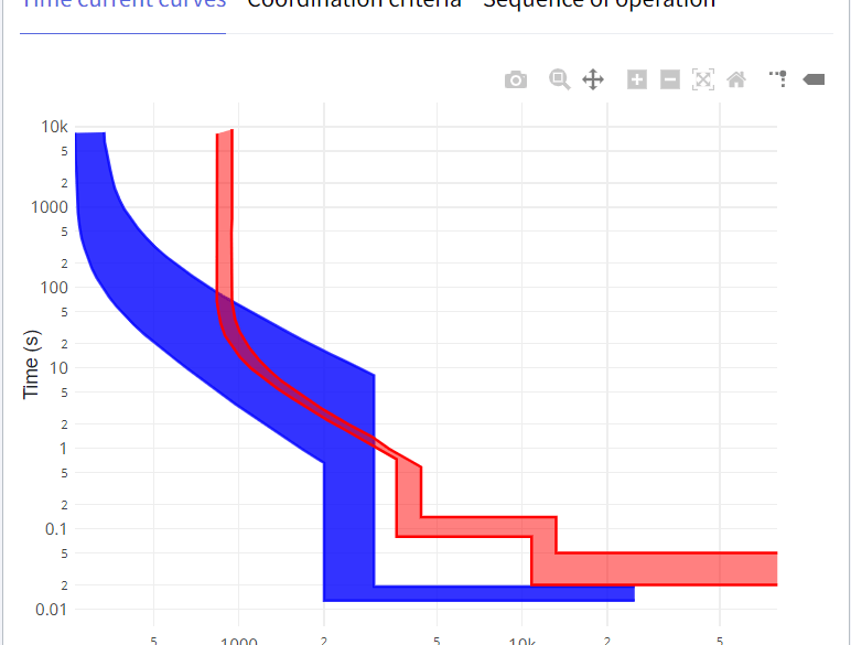
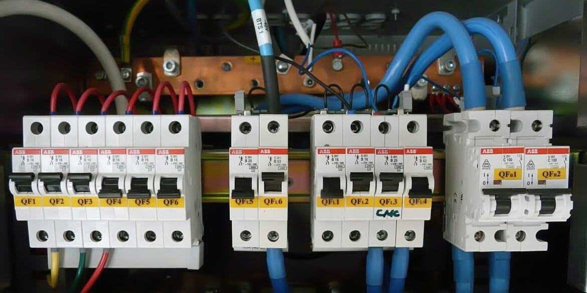
Miniature Circuit Breakers (MCBs) protect against overcurrent in electrical circuits. MCBs are categorised based on their tripping characteristics, represented by different device curves such as Z, B, C, K, and D. This article offers guidance on selecting the right type for your application.
The AS/NZS 3000 Standard provides different rules in Appendix C for maximum demand with socket-outlets for domestic, commercial, and industrial electrical installations. Calculation examples are provided involving double socket-outlets.
The principle of economic cable sizing is to select a minimum cable size that is safe to use and the cost of the losses over the lifetime is also minimised.
Equations for calculating conduit sizes and space factors in accordance with standards are provided. Worked examples of conduit sizing calculations are provided.

Print this article:

Print
Cable Pro Web Software
Cable Pro Web

Cable sizing, maximum demand, LV network design, protection coordination, cable pulling, and arc flash calculations.

As used by:

Cable Pro Web Clients