Table of Contents
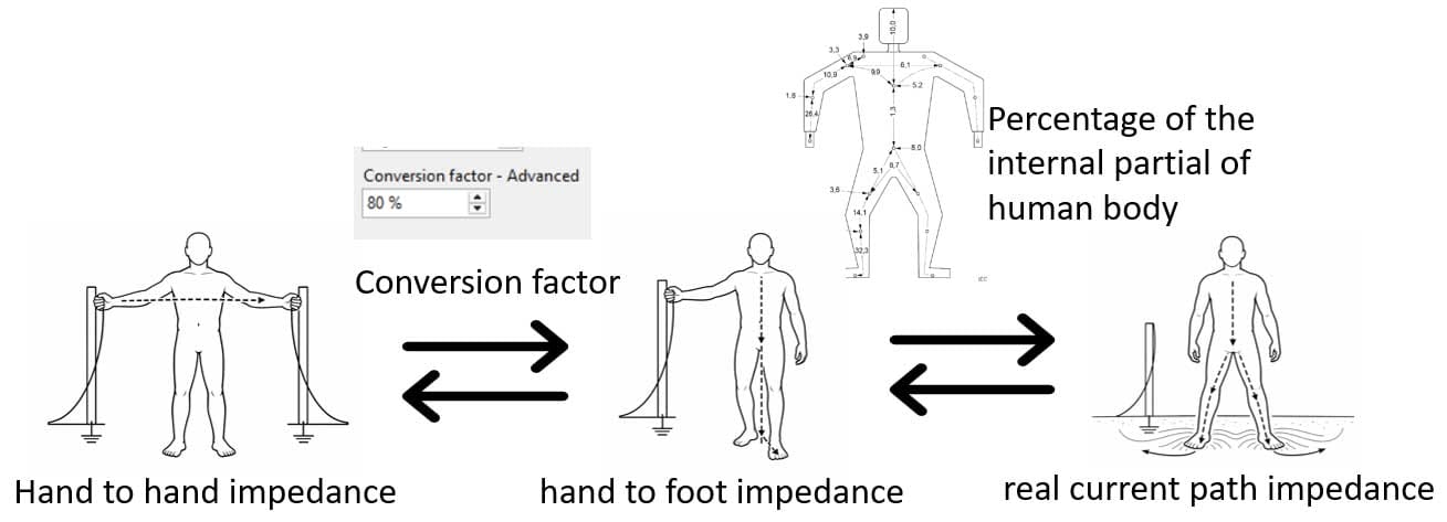
How the Conversion Factor Affects Permissible Touch Voltage
Touch voltage safety calculations depend on one thing above all: the impedance of the human body along the path the current actually takes. Each path has its own impedance, and each impedance gives a different permissible touch voltage.
The challenge is that IEC 60479-1 [1], the international reference for body impedance data, provides values only for the hand-to-hand path. To use that data for any other current path, we need a way to translate hand-to-hand impedance into hand-to-foot impedance. That translation is the Conversion Factor.
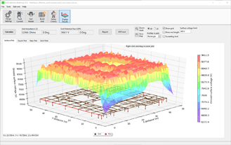
This article explains how the Conversion Factor is defined in IEC 60479-1, why it matters in earthing system design, and how different values change the calculated permissible touch voltage. A case study is included, performed in ELEK SafeGrid Earthing Software [2], comparing values of 70%, 80%, and 90% under otherwise identical conditions.
Body Impedance and the Current Path
In a real electrical shock, current rarely flows exactly hand-to-hand. The actual path depends on where the body is in contact with the energised surface and with the ground. Each path has its own effective body impedance, which directly determines the permissible touch voltage.
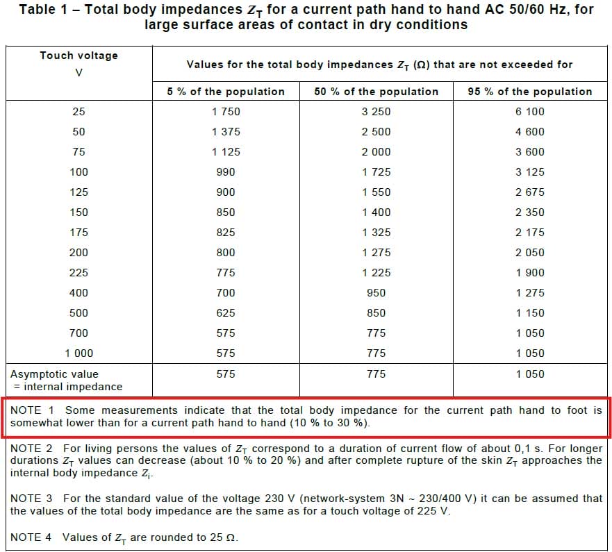
IEC 60479-1 measured total body impedance in the laboratory under tightly controlled conditions:
- Hand-to-hand current path
- Large contact area
- Dry skin
The standard then defines hand-to-foot as the working reference path for design calculations. All other current paths, such as foot-to-foot, hand-to-both-feet, etc., are derived from hand-to-foot using path-specific scaling factors.
What Is the Conversion Factor?
The Conversion Factor is the ratio of hand-to-foot body impedance to hand-to-hand body impedance:
\(\text{Conversion Factor} = \frac{Z_{\text{hand-to-foot}}}{Z_{\text{hand-to-hand}}}\)
It is applied to the hand-to-hand values published in IEC 60479-1 to obtain the hand-to-foot impedance used as the basis for all design calculations.
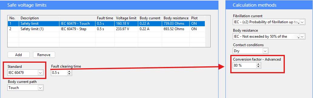
IEC 60479-1 specifies that hand-to-foot impedance is approximately 70% to 90% of the hand-to-hand value (10% to 30% lower). ELEK SafeGrid uses the midpoint of this range, 80%, as its default recommended value.
Why It Affects the Permissible Touch Voltage
Body impedance directly determines how much current flows through a person at a given touch voltage:
\({I_{\text{body}}} = \frac{V_{\text{touch}}}{Z_{\text{body}}}\)
Under any safety standard, the maximum allowable body current is fixed by the fibrillation current curve and the fault-clearing time. The permissible touch voltage is then calculated from that current and the body impedance:
- Higher impedance → higher permissible voltage limit (less conservative).
- Lower impedance → lower permissible voltage limit (more conservative).
A lower impedance value corresponds to a lower Conversion Factor and is the more conservative design choice, and vice-versa.
Case Study: Effect of the Conversion Factor on Permissible Touch Voltage
The following case study shows how the Conversion Factor alone changes the permissible touch voltage. All other parameters are held constant.
Calculation settings
- Fibrillation current: 50% probability of ventricular fibrillation
- Body resistance: IEC reference value (not exceeded by 50% of the population)
- Contact conditions: dry
- Fault clearing time: 0.5 s
Three Conversion Factor values are assessed: 70%, 80%, and 90%. The 80% value is the midpoint of the IEC 60479-1 range.
Hand-to-foot current path

| Conversion Factor | Permissible touch voltage | Body current |
|---|---|---|
| 70% | 195.02 V | 0.22 A |
| 80% | 215.74 V | 0.22 A |
| 90% | 236.39 V | 0.22 A |
The body current is identical across all three cases, set by the fibrillation curve and the fault duration, not by the Conversion Factor. Only the voltage limit moves.
Foot-to-foot (step) current path
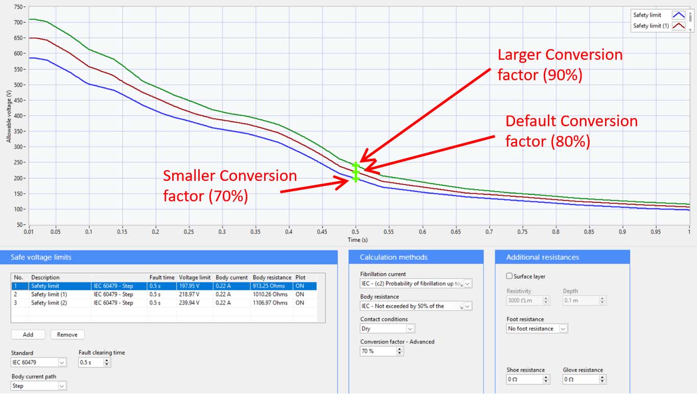
The same pattern appears in the step-voltage calculation:
| Conversion Factor | Permissible touch voltage | Body current |
|---|---|---|
| 70% | 197.95 V | 0.22 A |
| 80% | 218.97 V | 0.22 A |
| 90% | 239.94 V | 0.22 A |
Interpreting the results
- Lower Conversion Factor (e.g. 70%) → lower effective body impedance → tighter permissible voltage limit. More conservative design outcome; better protection for vulnerable individuals.
- Higher Conversion Factor (e.g. 90%) → higher effective body impedance → looser permissible voltage limit. Less conservative outcome; may not protect the most vulnerable.
The effect is consistent across both current paths.
Practical Guidance for Earthing Designs
- If unsure, use the IEC midpoint (80%). It is the recommended default and aligns with the centre of the IEC 60479-1 range.
- Use 70% when an extra margin is needed. For example, where vulnerable populations (children, the elderly, those with cardiac conditions) may be exposed, or where contact conditions cannot be fully controlled.
- Only use 90% with a clear justification. A higher Conversion Factor relaxes the design and may not protect the most vulnerable individuals.
- Document the value used. The Conversion Factor is an explicit design assumption and should be included in the earthing system design report alongside other safety-determining parameters (fibrillation curve, body resistance percentile, contact conditions, fault-clearing time).
Key Takeaways
- IEC 60479-1 tabulates body impedance only for the hand-to-hand current path. Hand-to-foot impedance must be derived first before any other current path can be calculated.
- The Conversion Factor is the ratio of hand-to-foot to hand-to-hand impedance.
- It directly shifts the effective body impedance and, therefore, the permissible touch voltage limit.
- The permissible body current depends only on the fibrillation current curve and fault duration, not on the Conversion Factor.
- The influence of the Conversion Factor is consistent across all body current paths.
- A lower Conversion Factor produces a more conservative design; a higher value relaxes the permissible voltage limit.
Frequently Asked Questions
What is the Conversion Factor in IEC 60479-1?
The Conversion Factor is the ratio of hand-to-foot body impedance to hand-to-hand body impedance. It is used to translate the hand-to-hand impedance values published in IEC 60479-1 into the hand-to-foot impedance used as the reference for earthing safety calculations.
What is the typical range of the Conversion Factor?
IEC 60479-1 states that hand-to-foot body impedance is approximately 70% to 90% of the hand-to-hand value. The midpoint (80%) is the recommended default in ELEK SafeGrid.
Does the Conversion Factor affect the permissible body current?
No. The permissible body current is determined solely by the fibrillation current curve and the fault-clearing time. The Conversion Factor only affects body impedance and, therefore, the permissible touch voltage.
Which Conversion Factor value gives a safer design?
A lower Conversion Factor (closer to 70%) results in a more conservative design, as it reduces the effective body impedance and tightens the permissible touch voltage limit. A higher value (closer to 90%) relaxes the limit and produces a less conservative outcome.
Why does IEC 60479-1 use hand-to-foot rather than hand-to-hand as the reference for design calculations?
Hand-to-foot is the most representative current path for typical electrical shock scenarios encountered in practice. It is therefore the natural baseline from which other current paths (such as foot-to-foot for step voltage) are derived.
References
[1] IEC 60479-1:2018 Effects of current on human beings and livestock – Part 1: General aspects. International Electrotechnical Commission.
[2] ELEK SafeGrid Earthing Software, Version 9.5. Available at https://elek.com/electrical-software/safegrid-earthing.