Table of Contents
Problem to solve - 13 kV circuit crossing with 400 kV circuit
New 13 kV power circuits to be installed in an unfilled trough with ventilated covers. These new circuits will cross with existing buried 400 kV cables at approximately 90 degrees with a continuous current rating requirement of 1136 MVA (1640 A) per phase for all seasons.
What will be the derating caused by the new 13 kV cables on the 400 kV cables?
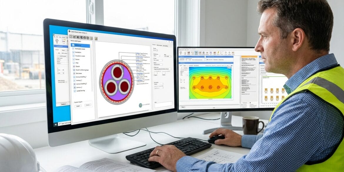
The calculations were performed using ELEK Cable High Voltage™ Software

Unfilled trough cable current ratings
It is common practice to install cables in air-filled troughs inside substations. For unfilled troughs with solid lids, where the lids are fitted to protect the cables from mechanical damage and solar radiation, there will be an increase which is often significant, in the air temperature inside the trough. This is because the trough cover stops the circulation of cool ambient air inside the trough, and the heat generated by the cables inside the trough must be entirely dissipated through the solid walls of the trough. There are equations provided in the IEC 60287 Standard for calculating the increase in air temperature inside the trough caused by the cables.
For unfilled troughs with ventilated covers, resulting in natural ventilation, to maximize the current rating of the cables in troughs. Once the lid is removed from the trough, the ambient air can circulate inside the trough, and the hot air can escape. Note that the thermal behavior of the air inside a ventilated trough containing power cables is complicated and that the IEC standard does not provide equations for these situations. A general rule of thumb used by the electrical industry states the current rating of cables installed inside air-filled and uncovered troughs would be 90 % of the current rating that it would have in free air.
Finite element modelling of ventilated troughs
A recent study [reference 3] used the finite element method (FEM) to model the complex flow of air inside unfilled troughs. The main findings of the study are:
- The current rating of cables in naturally ventilated troughs was increased by up to 28 % compared with covered troughs.
- The rating of cables in ventilated troughs may be assumed 90 % of the continuous rating of IEC 60287 Free Air (solar-shielded), provided that the grill design prevents solar radiation from entering the trough.
Note that additional maintenance may be required to ensure the troughs and grilles remain clear of leaves and debris so they remain properly ventilated.
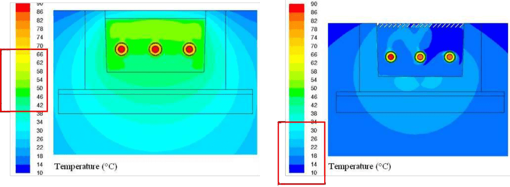
Unfilled Trough Temperatures
Solution to the problem
There is evidence to suggest, through the FEM modelling above, that for an unventilated trough, around 10 % of the total heat generated by the cables inside the trough would be transferred to the remote ground via the trough walls.
Therefore a solution to the rating problem as follows:
We can consider that the losses (P) are related to the current (I) using the relation P = I2R and assuming resistance (R) is fixed.
The current of the 13 kV cables in the ventilated trough corresponding to 10 % of the losses would be sqrt(0.1)*load current.
For example, if the load current is 599 A, the reduced current corresponding to 10 % losses would be 0.31623 * 599 = 189.4 A.
The results of the analysis are summarised in the table below.
| Case - Condition | Installation conditions | Current ratings | 1 | 400 kV (2000 mm2) isolated circuit |
Buried at 0.85 m depth in 250 mm ducts. Spaced at 600 mm. Native soil 1.2 K.m/W Backfill 1.2 K.m/W Ambient soil temperature 15 ˚C |
1664 A @ 90 ˚C |
|---|---|---|---|
| 2 | 13 kV (300 mm2) isolated circuit |
Ventilated trough at 0.2 m below ground level. Modelled as 90 % of the in air rating using IEC 60287. |
599 A @ 90 ˚C |
| 3 | 400 kV (2000 mm2) and 13 kV (300 mm2) in parallel |
400 kV circuit modelled as per Case 1 above. 13 kV circuit direct buried at 0.2 m carrying 189.4 A |
1655 A @ 90 ˚C - 400 kV circuit 189.4 A @ 20 ˚C - 13 kV circuit |
When the 13 kV cables carry only 189.4 A, the conductor operating temperature is around 20 ˚C (only 5 ˚C above ambient temperature). The additional heating from the 13 kV inside the ventilated trough is relatively minimal, resulting in a current rating reduction of 9 A (derating factor of 0.9946) for the worst case when both the 13 kV and 400 kV circuits are in parallel.
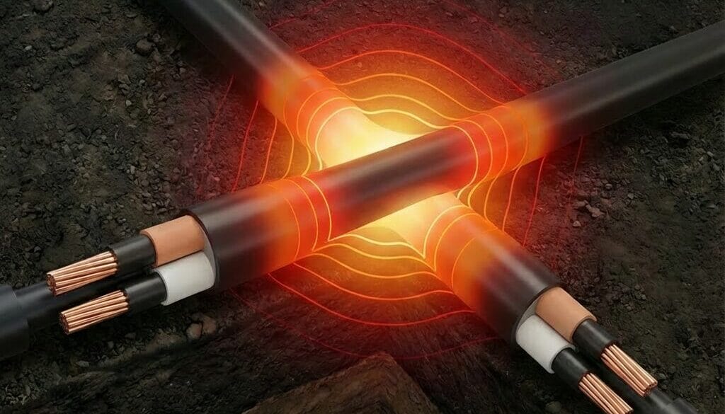
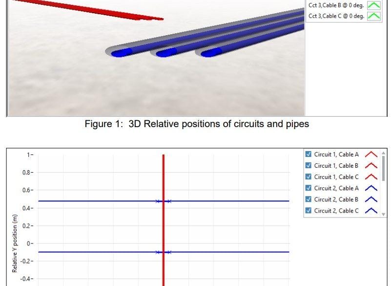
Cables crossing calculations at 90 degrees
From our theory on cable crossings calculations, we know that the mutual heating between circuits is the lowest when cables cross at 90° and worst when they are parallel.
Refer to our Technical Article on Cable Crossing Calculations for more information.
We could use the Cable Crossings module of ELEK Cable HV Software to show at a 90° crossing angle; the derating from the 13 kV circuit is practically negligible.
References
[1] IEC 60287 “Electric cables – Calculation of the current rating, Part 2-1: Thermal resistance – Calculation of thermal resistance” (2015).
[2] IEC 60287 “Electric cables – Calculation of the current rating, Part 3-3: Sections on operating conditions – Cables crossing external heat sources.” (2007).
[3] Rating of Cables in Unfilled Surface Troughs, Pilgrim. J.A. et al., IEEE Transactions 2012.