Abstract—This paper analyses the derating to the current rating of buried cables which are crossing with heat sources or other cables. Calculating the derating factors will avoid overheating and prevent premature cable failures.
A software algorithm has been developed which can determine the derating factors for multiple cable circuit crossings or heat sources. The derating factor(s) obtained from the calculations are multiplied by the isolated rated current of the cables (also calculated).The methods described herein are based on IEC Standard 60287 and use Kennelly’s principle.
Index Terms: Cables, derating factor, current-carrying capacity, mutual thermal resistance, attenuation factor.
Table of Contents
I. INTRODUCTION
The calculation of cable current rating requires a solution of the heat transfer equations, which define a functional relationship between the conductor current and the temperature within the cable and in its surroundings .The IEC Standard 60287 [1] defines procedures and equations for determining the current rating.
Part 3-3 of the Standard provides a method for calculating the effects on current ratings for cables which cross one another or with other external heat sources like steam pipes. When cables cross one another, this will increase the temperature of the cable and hence the current carrying capacity of that cable will be reduced. The temperature increase depends on the following parameters:
- The amount of heat generated by the source. Where the heat source is another cable or multiple cables, then the heat generated is proportional to the current carried.
- The cross-sectional area of the cable conductor.
- The distance between the cable and heat source.
- The angle of the crossing(s). The derating is the least when cables cross at 90° and worse when they cross at smaller angles.
The temperature rise is maximum at the crossing point and decreases away from the crossing. Due to the varying temperature rise along the cable length, a longitudinal heat flux is generated in the conductor because of this crossing. If the longitudinal heat flux is ignored the conductor temperature rise at the crossing point will be much higher which might result in a lower current rating. After a certain distance away from the crossing along the cable route, the effect of longitudinal flux becomes negligible.

Fig. 1: Single core cables crossed by a multicore cable
II. SOFTWARE ALGORITHM
This section provides the pseudocode for an algorithm used to derive the derating factors of the cables. Two sets of code are explained below –
A. When a single heat source crosses a cable.
B. When multiple heat sources cross a cable.
A. Derating factor – Single heat source crossing Derating factor – Single heat source crossing
A cable can be de-rated due to the single heat source crossing with the cable for example a steam pipe. The heat generated by the steam pipe is a function of the surface temperature of the pipe. The steps to be followed in calculating the derating factor in this case is as follows.
- Calculate current ratings of the cables in isolation for all the cables in the system. We use Cable HVTM software for this.
- Calculate an attenuation factor which is the change in longitudinal heat flux with total thermal resistance of the conductor.
- Calculate an initial estimate of the temperature rise of the conductor(s) of the rated cable, due to crossing of heat sources, at the hottest point on the cable.
- Calculate a first estimate of the mutual thermal resistance.
- Estimate the increase of temperature rise of the cable caused by the crossing.
- Calculate a derating factor.
- Continue steps 2 to 6untilderating factor converges. B. Derating factor – Crossing of multiple heat sources
The derating factor can be generalized for several heat sources crossing the rated cable by applying the principle of superposition. The method of calculating derating factor remains same as for a single heat source (above), but the first estimate of the mutual thermal resistance must be repeated for each heat source. The steps to be followed are outlined below for 2 circuits.
- Calculate current ratings of the cables in isolation for all the cables in the system .We have used Cable HVTM Software for this.
- Calculate the z position where the temperature will be at its maximum.
- Calculate the derating factor and de-rated current for circuit 1 (perform steps as 2-6 as outlined above for a single heat source) if other circuits carry their isolated rated current.
- Calculate the Joule losses for the circuit 1 due to the de-rated current.
- Using the de-rated current for circuit 1, calculate the derating factor and de-rated current for circuit 2.
- Calculate the Joule losses for the circuit 2 due to the de-rated current.
- Repeat steps 2-6 above until both the derating factors converge.
III. EXAMPLE CALCULATIONS
The simulations are carried out for a single cable crossing a steam pipe, a multicore circuit crossing a three-phase single core circuit and multiple circuits composed of single c ore and multi-core cables crossing each other. The steady-state current ratings of the isolated cable circuits were calculated using Cable HV™ software.
A. Example 1 – Single cable crossing a steam pipe
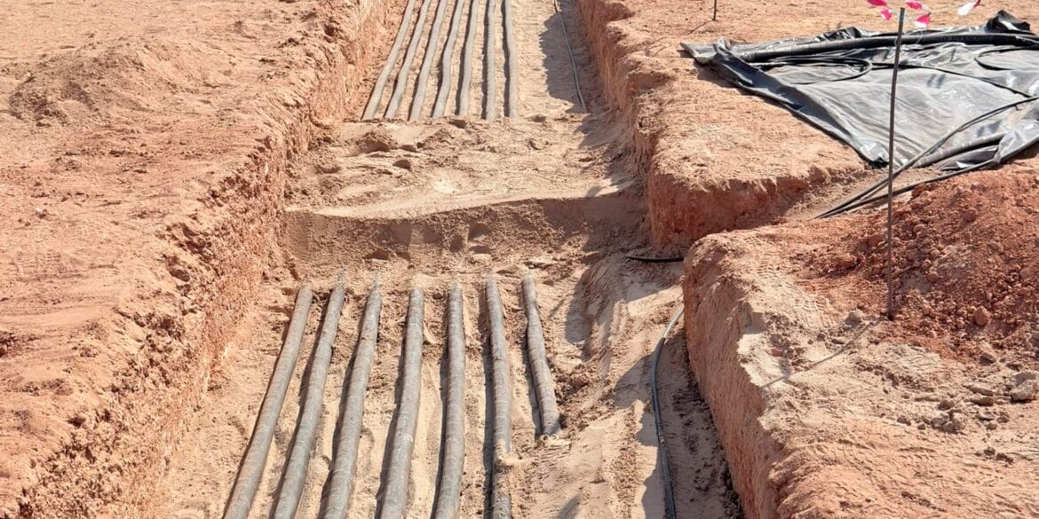
An example calculation was performed for a single cable crossing a steam pipe as shown in Fig. 2.
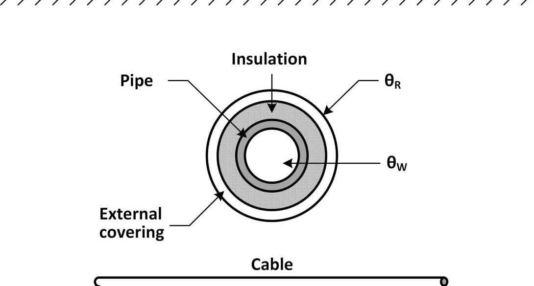
Fig. 2: A steam pipe crossing a cable.
The heat generated by the steam pipe can either be entered manually or calculated by the software iteratively. The inputs required for the calculation of the heat generated are the thermal resistance of the pipe insulation, the fluid temperature inside the pipe, and the outer diameter of the pipe. The solution for the heat generated, obtained after 5 iterations is 78.87 W/m and the crossing angle is varied from 30° to 90°. The conductor size is 2000 mm2 and the cable is buried at 1.8 m below the ground surface. Cable HVTM Software calculated the isolated current carrying capacity to be 1365 A for a soil resistivity of 1 Cm/W at an ambient soil temperature of 25 °C. The derating factor converged after 3 iterations.
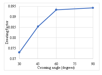
Fig. 3: Variation of derating factor with crossing angle
Figure 3 shows the de-rated current rating of the cable due to crossing of the steam pipe between the angles of 60° and 90° (relatively flat) is better than at 45° or 30°.
B. Example 2 – Single core 10 kV cables circuit crossing a three-phase multicore 145 kV cable
This example is based on the example calculation in Appendix A of IEC Standard 60287-3-3. Figure 1 shows the installation involves three-phase circuits comprising single core cables (Circuit 1) crossing with a three-phase multicore cable (Circuit 2). The single core cables are buried at 1.2 m while the multi-core cable is buried at 0.9 m. The conductor area for the multicore cable is 400 mm2 and that of the single core cable is 300 mm2. The current carrying capacity of the isolated circuits are 665 A and 585 A, respectively, at a soil thermal resistivity of 0.8 Cm/W and an ambient soil temperature of 25 °C.
Since the cables in circuit 1 are symmetrical and the losses are same, the position where the maximum temperature occur will be the same as the hottest cable position. But if any of the above factors such as symmetry or losses are different, then the software uses a weighted average method to find the point of maximum temperature. The derating factors and de-rated currents were calculated for different crossing angles (shown in Fig.4 and Fig. 5). The derating factors converged after 4 iterations.
The calculations of the mutual thermal resistance of the right cable in the single core cable circuit (page 16, Table A3) in Standard IEC 60287 3-3 [1] is incorrect. The value in the standard is 0.174, and the value we obtain is 0.156.
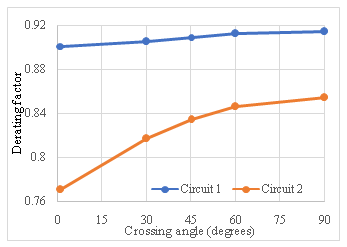
Fig. 4: Variation of deratingfactor with crossing angle
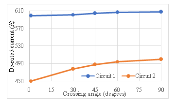
Fig. 5: Variation of de-ratedcurrent with crossing angle
C. Example 3 – Multiple (3 or more) circuit crossings
We have developed a software algorithm capable of determining the derating factor for multiple cable crossings. There can be any number of cables at any depth which are crossing at any relative angles. When multiple circuits are considered a combination of the above pseudo codes are used depending on the total number of heat sources. All the cables are simultaneously de-rated, and the software provides the derating factor and de-rated current for all the circuits.
In the following two examples involving multi-circuit cable crossings we calculate the derating factors of all circuits. The position where the maximum temperature occurs is calculated by weighing the losses with the positions of cables that form the heat source. Fig. 6 depicts the arrangement for the first example comprising three buried circuits: two multicore circuits and one single core circuit. The multicore cables both cross with the single core circuit at an angle of 90° but at different depths.
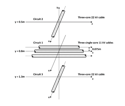
Fig. 6: Positions of cables where the multicore cables cross the single core cable at 90°
Fig. 7 depicts the arrangement for the second example which is the same as the first example except that the multicore Circuit 2 crosses the single core circuit at an angle of 45°.
The single core cables for these examples have a conductor area of 300 mm2 while the multi-core cables had an area of 500mm2. The single core cables (Circuit 1), are laid at 0.8 m below the ground surface and arranged in a flat formation with a spacing of 0.075 m between the cable centers. Circuit 2 is a multicore cable buried 0.3 m above the single core cables whilst Circuit 3, also a multicore is buried 0.5 m below the single core cables.
Firstly, the isolated current rating for all cable circuits are determined using Cable HVTM Software. The isolated current ratings of the three circuits are calculated to be 532 A, 690 A and 625 A for Circuits 1, 2 and 3, respectively.

Fig. 7: Circuit 2 crossing Circuit 1 at 45° and Circuit 3 crossing Circuit 1 at 90°
The plot in Fig. 8 indicates the final derating factors are 0.842, 0.877 and 0.848 for Circuits 1, 2 and 3, respectively and convergence is achieved within 5 iterations. Therefore Circuit 1 which is the single core circuit in the middle of Circuits 2 and 3 is de-rated the most, which is to be expected.
The plot in Fig. 9 indicates the final derating factors are 0.828, 0.875 and 0.865 for Circuits 1, 2 and 3, respectively. Therefore, when the crossing angle of Circuit 2 is changed to 45° the derating of Circuit 1 (single core cables) is worsened and that of both Circuit 1 and Circuit 3 are improved.

Fig. 8: Derating factors for each iteration with Circuit 2 and 3 crossing Circuit 1 at right angles
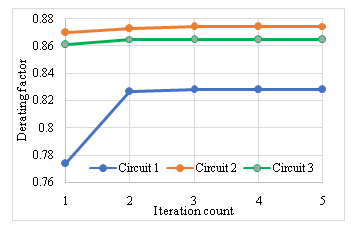
Fig. 9: Derating factors for each iteration where Circuit 2 and Circuit 3cross Circuit 1 at 45°and 90° respectively
IV. CONCLUSION
The software algorithm developed for derating factor calculations provides an easy and fast solution in calculating the continuous current carrying capacity of the cables when crossed with other cable or with heat sources. The derating of the cables prevents over heating and premature damage to the cables. The results presented show the effect of various parameters such as angle of crossing of the heat source, size of cables under study and the distance between the heat source and the cables affect the derating factor.
V. References
[1] IEC,60287 “Electric cables – Calculation of the current rating, Part 3 3: Sections on operating conditions – Cables crossing external heat sources.”(2007).