Table of Contents
Introduction
In the field of electrical power engineering, the standard HV cable rating calculation methods do not cover all real-world situations.
This article proposes a new method of finding the current rating for 10 cables touching in the air.
We’ve used ELEK Cable HV Software and standard calculation methods for 3 cables to estimate the rating for 10 cables using curve fitting with extrapolation.
The result is a reasonably accurate current rating, validated by reliable data.
Problem
Our task is to determine an accurate current rating for a group of custom 10 x medium voltage 95 mm2 power cables that are touching and installed in air. The problem is this configuration is not (directly) covered by the analytical equations provided by IEC 60287.
Note that this complicated situation is avoided by separating the cables by at least a cable diameter. Refer to the article Current Rating for Groups of Circuits Installed in Air [ref. 5].
Methodology
For individual circuits the calculations are performed according to IEC 60287-2-1 [ref. 2] for a standard set of configurations. For groups of circuits installed in air the calculation is based on IEC 60287-2-2 [ref. 3], with the calculations limited to standard group configurations.
A multi-step software calculation technique will be used to solve the problem as follows. A model of the actual multicore power cable will be used.
- Calculate the current rating of a single cable in air (CR1).
- Calculate the current rating of 2 groups (CR2) and 3 groups (CR3) of touching cables (side-by-side).
- Determine two derating factors with respect to CR1 for the groups of 2 and 3 cables:
- DF2 = CR2/CR1; DF3 = CR3/CR1
- Fit a logarithmic curve to the derating factors and extrapolate to 10 touching cables. The result is a derating factor DF10 which can be multiplied by CR1.
An alternate method is to perform the first step to obtain CR1 and then use a derating factor from the tables in standard AS/NZS 3008.1 [ref. 4]. But, this may be overly conservative.
Cable modelling
The cable used in this document is an XLPE insulated 11 kV cable with copper conductor and PVC jacket. External diameter of the cable = 64.1 mm.
Results – Calculation of a derating factor
Using the methodology, the predicted derating factor for 10 multicore touching cables is 0.85. Therefore, the derated current rating would be 220.54 A.
Table 1. Current rating and derating factor table for 95 mm2 multicore cable in different arrangement.
Case no. | Installation method | Current rating | Derating factor |
---|---|---|---|
1 | Single cable spaced from surface. | CR1 = 259.46 | |
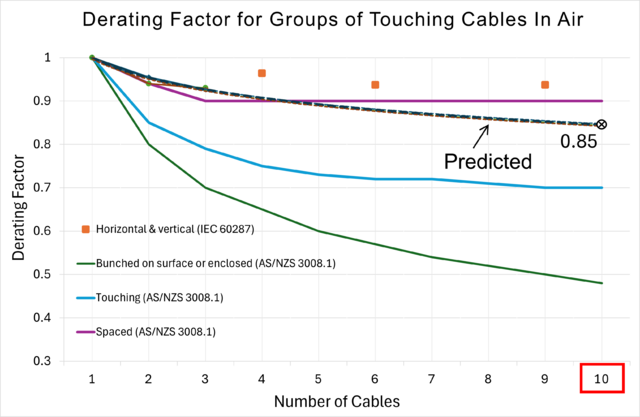
2 | Two multicores side-by-side and touching (e = 0 m). | 
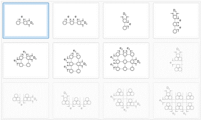
CR2 = 247.83 | DF2 = 0.95 |
3 | Three multicores side-by-side and touching (e = 0 m). | 
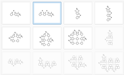
CR3 = 240.60 | DF3 = 0.92 |
4 | Ten multicore cables in air side by side and touching (predicted current rating). | CR10 = 220.54 | DF10 = 0.85 |
Validation
Comparisons with large cables and single core cables
This case study was for a small multicore cable type. We also calculated the derating factors by performing the same steps outlined in the methodology for large conductor size (630 mm2) as well as single core cables. We found that large single core cables in air in groups are derated the most but still only slightly more than small cables
Comparisons with derating factors from standards
The derating factors for groups of cables in air from the standard AS/NZS 3008.1 [ref. 4] are compared and found to be conservative with respect to our predicted current rating using software.
Comparison of vertically arranged cable groups
The standard IEC 60287-2-2 [ref 3] provides ratings for up to 4-9 multicore circuits, but these are arranged vertically in rows of three. We compared these ratings and found they were much higher than those predicted by our method for side-by-side cables. This is because for these arrangements the horizontal mutual heating effects are negligible (since the circuits are assumed not to be touching on their sides), and only vertical heat flow and mutual heating are considered.
It turns out that horizontally touching cables are derated more due to mutual heating than vertically touching cables.
Conclusions
Direct calculation methods may not be available for every installation condition. For complex installation conditions, utilising a multi-step calculation approach and combining several of the available methods, one can reach a reasonable approximation of the current rating. It is also advisable to collect and compare data from other sources for validation purposes.
Of course, your engineering judgment is required to decide whether this method or any other method is sound and appropriate.
References:
[1] ELEK Cable HV Software, V6.5.
[2] IEC 60287-2-1 Electric cables – Calculation of the current rating – Part 2-1: Thermal resistance – Calculation of thermal resistance.
[3] IEC 60287-2-2 Electric cables – Calculation of the current rating – Part 2: Thermal resistance – Section 2: A method for calculating reduction factors for groups of cables in free air, protected from solar radiation.
[4] AS/NZS 3008.1:2017 Electrical installations — Selection of cables, Part 1.1: Cables for alternating voltages up to and including 0.6/1 kV — Typical Australian installation conditions.
[5] Current Rating for Groups of Circuits Installed in Air, https://elek.com/articles/current-rating-groups-in-air-different-voltages/.