0

Your Cart

0
Subtotal: AUD0
No products in the cart.

Cable Current Rating Derating Factors Explained

Cable Current Rating Derating Factors Explained

Derating factor theory is explained and standard derating factor tables are provided
The high voltage electrical cables are laid in a trench_ELEK Software

Why are cables derated?

The current rating of a cable is affected significantly by the installation conditions and the external environment. For example, cables may be installed in air or buried underground and will have a different current rating. In general, the same cables when installed in air have a higher current rating than when they are buried. The ambient temperature of the air or soil also affects current rating.

There are so many possible installation conditions and different environmental conditions. Therefore, the Standards for low voltage cable sizing such as AS/NZS 3008.1, BS 7671, and IEC 60364-5-52 provide current ratings tables for fixed (standard) installation conditions.

These standards also provide derating factor tables to be applied to the cable current ratings when the actual installation conditions for your project differ from the standard conditions. These derating factors most often reduce, but sometimes increase, the effective current carrying capacity for your cables ensuring that the temperature limits for those cables are not exceeded.

You can determine derating factors directly from the tables in the standards or using Cable Pro Web Software has a simple-to-use Wizard for derating factors.

The main factors that derate cables

The following nine (9) main factors affect (derate or uprate) the current rating of cables.

Ambient temperature – The current rating of a cable depends on the difference between the ambient temperature and the temperature limit for the cable. Therefore the same cables installed in colder environments will have a higher current rating than for the cables in hot environments.

Different countries have different standard ambient temperatures to be used for cable current ratings and these can be obtained from IEC 60287-3-1 for specific countries.

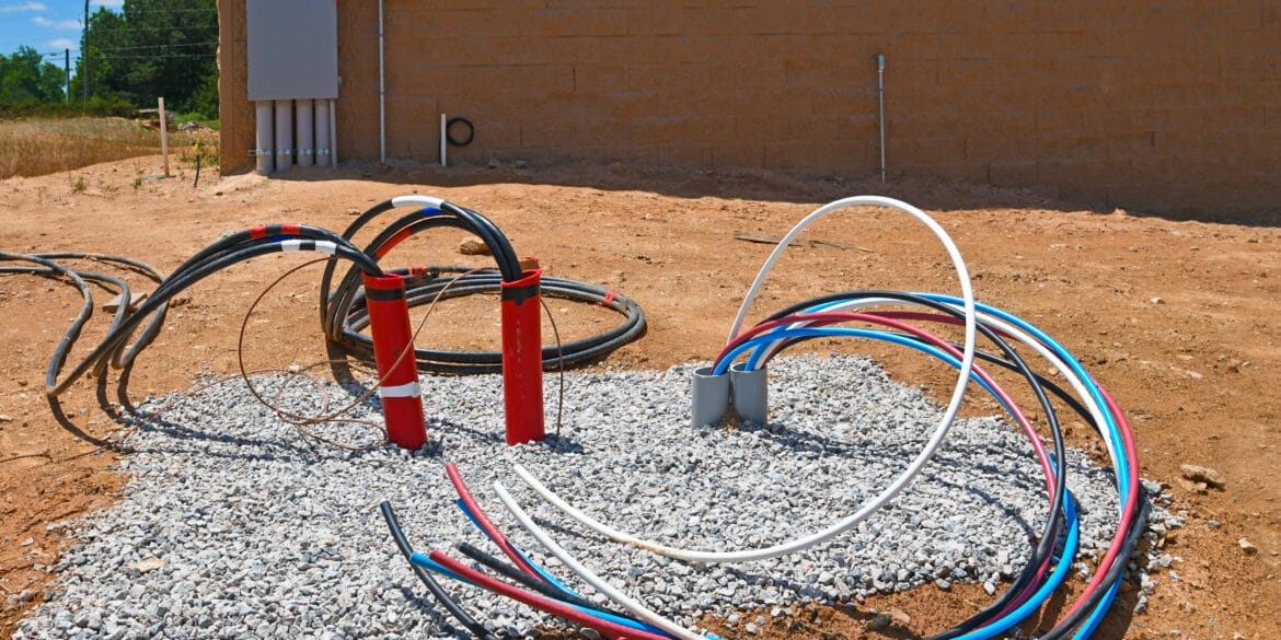
Depth of burial – The depth a cable is buried affects it’s ability to dissipate heat and therefore is a strong determinant of the current rating. Cables that are buried at deeper depths get hotter and therefore need to be derated. A typical depth of burial for low voltage cables is 0.5 metres (or 0.7 metres is assumed for BS 7671).

Thermal resistivity of soil – For buried cables one of the main factors that affects the current rating is the soil thermal resistivity which varies depending on soil composition, moisture content, seasonal weather patterns, and is affected by the loading of cables causing dry-out of soils.

A typical soil thermal resistivity is 1.2 K.m/W but varies between 0.8 K.m/W for clay or peat soils, and up to about 2.5 K.m/W for well-drained (low moisture content) soils with heavily loaded cables.

Varying loads (load factor) – Generally it is assumed by the low voltage cable sizing standards that the cables are continuously loaded, however when that is not the case then the current rating of the cables can actually be uprated.

Thermal insulation – The presence of thermal insulation around cables restricts their ability to dissipate heat and therefor derates the cables.
 
Direct sunlight – Exposure of a cable to direct sunlight has a very significant affect on the current rating. A rule of thumb is the sun will increase the cable temperature by 20 degrees Celsius.

Harmonic currents – The presence of third harmonic currents will cause additional joule losses in the cables which causes additional heating resulting in a derating of the current rating.

Groups of parallel circuits (mutual heating) in air (on trays or ladders) or buried – Cable circuits installed in proximity to other cable circuits will mutually heat one another and this mutual heating needs to be accounted for with derating factors for grouping of circuits.

Enclosures – Installing cables in enclosures results in additional heating which effectively derates the cables. When cables are installed inside the same enclosure (conduit) the derating will be worse
 

When can derating factors be avoided?

Interestingly, there are certain conditions when derating factors don’t need to be applied. The standard AS/NZS 3008.1 provides examples of these including:
 
(a) Mineral insulated (MIMS) cables without serving unless other types of cables are installed in close proximity or within the same wire enclosure.

(b) Limited length of grouping where length does not exceed and whichever is shorter:
(i) 1 m for conductor sizes < 300 mm2 aluminium or < 150 mm2 for copper; or
(ii) 3 m for conductor sizes 300 mm2 or larger aluminium and 150 mm2 or larger for copper; or
(iii) half the length of the cable.

(c) Cables operating at less than 35 % of their rated current capacity.

Note that since the current rating tables for all low voltage cable sizing standards mentioned above are derived based on the IEC 60287 standard methods then in general the ratings and derating factors from all standards can be interchanged – but be careful about the assumed standard conditions. For example the standard ambient temperatures in Australia are higher than in the United Kingdom.

How to use derating factors

It’s simple to use derating factors.

1. Obtain the current rating based on the standard conditions.

2. Determine the factors from the derating factor tables for your installation conditions.

3. Multiply all of the derating factors together and then multiply this value by the standard (tabulated) current rating of the cable to obtain the derated cable current rating. 

Low voltage cable derating factors -
Australian and New Zealand conditions

Derating factor tables

The derating factor Tables below are from both AS/NZS 3008.1.1 (Australian conditions) and AS/NZS 3008.1.2 (New Zealand conditions). The Tables from both standards are the same except for TABLE 27(1) and 27(2) which differ.

Disclaimer: No responsibility is assumed for the accuracy of the Tables below. Further, there are additional notes to these tables that have not been included.

In Air - Derating factor tables for groups of bunched circuits, in trays or on cable ladders

A table displaying the number of wires in a circuit related to power.
Table 22
A table displaying the various electrical circuits.
Table 23
A table with a number of different electrical circuits.
Table 24

Ambient air temperature and concrete slab temperature derating factor tables

A software-based rating system for renewable energy concrete slabs with embedded cables.
Table 27(1)
A table with substation ratings.
Table 27(1) - New Zealand

Buried - Soil ambient temperature, buried in enclosures and thermal resistivity of soils derating factor tables

A table with information on rating factors for renewables.
Table 27(2)
A table displaying soil temperature.
Table 27(2) - New Zealand
A table with a number of electrical rating factors.
Table 29

Buried - Direct buried cable derating factor tables for groups of single core and multicore cables, and depth of burial

A software displaying the quantity of electrical circuit groups in a substation.
Table 25(1)
A table with electrical factors for a group of circuits.
Table 25(2)
A table displaying various power ratings.
Table 28(1)

Buried - In enclosures for groups of single core and multicore cables, and depth of burial derating factor tables

Deriving electrical factors for groups of circuits using software.
Table 26(1)
A software table illustrating various electrical circuits in a substation.
Table 26(2)
A software application for analyzing rating factors in power substations.
Table 28(2)
Cable Pro Web

Cable sizing and maximum demand software in the cloud. No installation, use on any device.

Related Articles:

Size active, neutral, and earth cables using AS/NZS 3008. The guide covers current capacity, voltage drop, and short-circuit calculations with examples.
Miniature Circuit Breakers (MCBs) protect against overcurrent in electrical circuits. MCBs are categorised based on their tripping characteristics, represented by different device curves such as Z, B, C, K, and D. This article offers guidance on selecting the right type for your application.
The AS/NZS 3000 Standard provides different rules in Appendix C for maximum demand with socket-outlets for domestic, commercial, and industrial electrical installations. Calculation examples are provided involving double socket-outlets.
The principle of economic cable sizing is to select a minimum cable size that is safe to use and the cost of the losses over the lifetime is also minimised.
Equations for calculating conduit sizes and space factors in accordance with standards are provided. Worked examples of conduit sizing calculations are provided.
The fault current which flows in a power cable causes its temperature to rise dramatically. The adiabatic equations for calculating the minimum conductor size to withstand the short circuit are explained.

Print this article:

Print
Cable Pro Web Software
Cable Pro Web

Cable sizing, maximum demand, LV network design, protection coordination, cable pulling, and arc flash calculations.

As used by:

Cable Pro Web Clients